Description
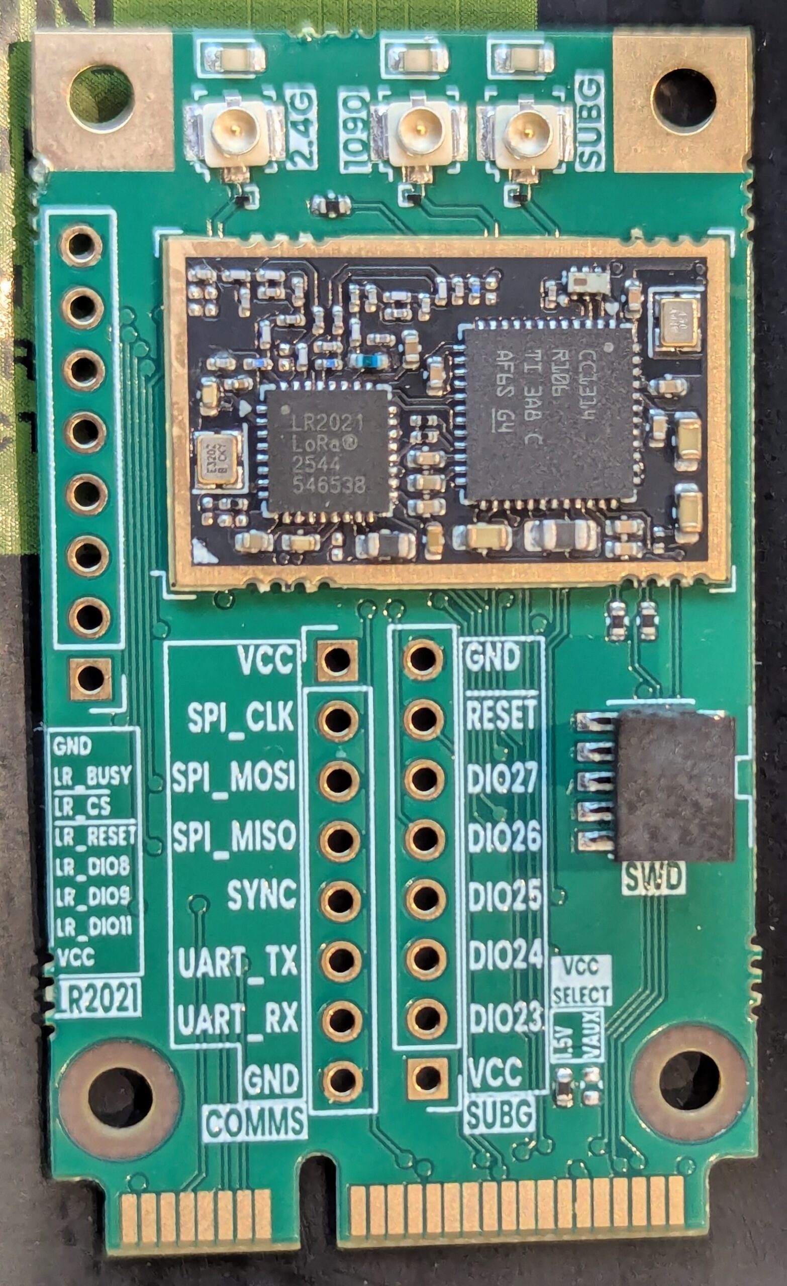
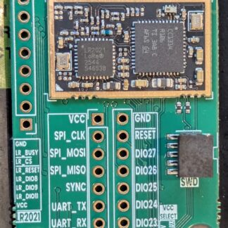
This evaluation kit for the ADSBee m1421 module includes an ADSBee m1421 with Sub-GHz, 1090, and 2.4GHz ports broken out onto an mPCIe card with a custom pinout. Jumpers allow selection of the operational voltage level of the ADSBee, as well as enable / disable for various indicator LEDs.
Kit Contents
- m1421 mPCIe module
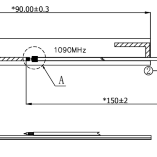
- 1x 1090MHz PCB antenna
- 1x 978MHz PCB antenna
By default, the evaluation kit comes with all LEDs enabled, and 1.5V mPCIe logic power selected. It is easiest to operate by connecting to power and UART via the pin headers (included, but not soldered).
SWD access to the CC1314 is provided via a 10-pin SWD header for firmware flashing and breakpoint debugging.
The m1421 mPCIe module comes pre-flashed with firmware. Updated firmware binaries will be made available as they are produced. Firmware and schematics for this product will be open sourced to the main adsbee repository once mass production begins.
This kit ships without an EMI can installed on the m1421 module. In mass production m1421 modules will be available with an EMI can (default), or without (for customers who want to shield over the module + pad connections).
WARNING: The mPCIe module pinout is non-standard. Do not use it with a standard mPCIe socket. Consult John (john@pantsforbirds.com) if you plan to use it this way.
WARNING: The power selection jumpers say 1.5V and 1.8V, but minim operational voltage for the m1421 is 1.8V. This is a vestige of the mPCIe power pins being selected by the 1.5V jumper being labelled as “1.5V” in the standard pinout definition.
Reviews
There are no reviews yet.