This last month has been another solid wave of progress! ADSBee 1090 Rev F is looking good and I’m excited to see it move into low volume initial production very soon. Scroll to the end for an update about the ADSBee Beta! 🎉
Hardware Updates
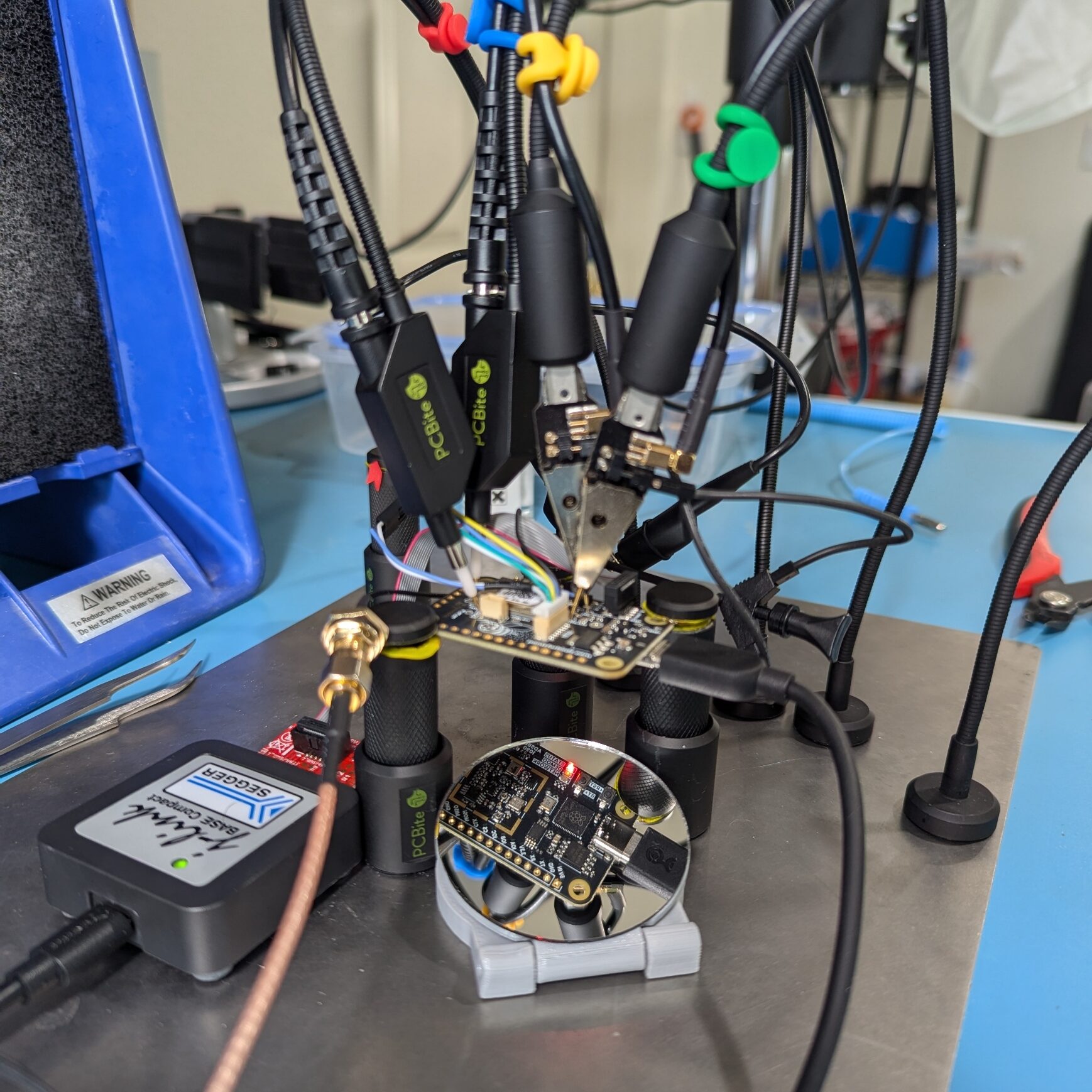
ADSBee 1090 Rev F Bringup
Bringup of revision F of the ADSBee 1090 has proceeded quite smoothly! There were a few hiccups (I had the wrong component installed by the manufacturer for the bias tee switch MOSFET, and some of the components that I’ve had to manually populate have been difficult to solder down properly), but overall the board seems to function as intended. Major changes in this revision include:
- Redesigned RF frontend with new layout and extra gain + SAW filter stage.
- Completely redesigned analog circuit implementing a data slicer topology.
- Upgraded to a newer ESP32 (ESP32-S3).
- Rewired the inter-processor communication bus to not accidentally use reserved pins on the ESP32.
- Added a USB JTAG debug connector for programming the ESP32, and added a coprocessor SPI connector to enable addition of a UAT module at some point in the future.
- Redesigned RP2040 pinout to expose pins for a second PIO state machine from the preamble detector and demodulator PIO blocks.
With this many changes, I have been pleasantly surprised to not find any “deal breakers” so far! It appears that all 10 of the PCBs I received will be able to be used as functional devices for testing once they are fully assembled and tested.
ADSBee 1090 Rev F hardware should be sufficient for the needs of our hardware Beta! Most of the units I have hand-assembled will be used for testing internally, but a select few will be sent out to other developers participating in the Beta test. I currently am getting assembly quoted for an additional run of Rev F units, which will be made available for a larger beta as soon as I have an updated estimate of pricing.
ADSBee 3D Printed Enclosure
I designed a 3D printed enclosure for the ADSBee 1090, with enouh extra room to support an FPC WiFi antenna and external GNSS module, and openings for connectors and indicator lights, button flexures for the BOOT and RESET buttons, and an internal latch to keep it closed. It’s still a work in progress, but the OnShape designs are available below. Feel free to remix and improve the enclosure as you see fit! I’d love to hear about new designs.


Antennas and Cables
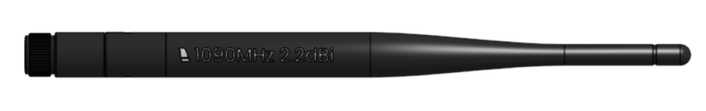
The 1090MHz sleeve dipole antenna has been redesigned to use a much smaller outer housing. This should make the full device more compact, and will have an added benefit of saving on shipping costs.
Waterproof SMA to U.FL cables have been sourced and tested, and are currently in 100x production to support the hardware beta. My intention is to include waterproof SMA to U.FL cables in order to allow ADSBee owners to easily connect their ADSBee to a 1090MHz antenna from within a waterproof enclosure. The cost difference between waterproof and non-waterproof SMA bulkhead connectors is relatively small, so it makes sense to standardize on a single cable part for waterproof and non waterproof enclosures in order to lower the unit cost.
Flex PCB WiFi antennas have also been sourced and tested. They will eventually need to be custom tuned for their installation location relative to the ADSBee 1090 PCB within the 3D-printed enclosure, but they should function just fine for the beta without the need for fine tuning.
Firmware Improvements
Additional Mode S Downlink Formats
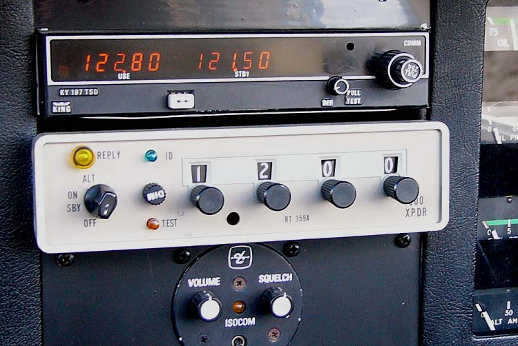
Decoding has been implemented for Mode S downlink formats 4 and 5 (Identity and Altitude replies). This was a bit of an adventure, and involved a fairly cursed exploration of how to decode Gillham Coded altitude information (old timey altitude encoders connected directly to transponders with a number of parallel wires, and used a novel binary protocol that was intended to only toggle a single bit at a time while incrementing or decrementing). Many thanks are owed to a kind British man named Kevin Stewart, whose old forum posts and online documentation described how to decode Gillham coded values in the context of his quest to build a DIY altimeter calibration device.
Gillham Codes have no built-in method of error checking, since a single broken wire in the bundle of wires between the altitude encoder and transponder can cause garbage altitude values to be transmitted. There is a single bit flag in the Mode S protocol that is dedicated to warning that a transponder’s altitude information may not be very robust, as it is based on a single reading from a Gillham coded altimeter.
Gillham coded transponder outputs (just a bunch o’ wires) have since been superseded by a number of more robust communication protocols between altimeters and transponders on aircraft (e.g. serial protocols with checksums), but for some reason the Gillham codes themselves are still used for encoding altitude data in 56-bit Mode S packets.
Decoding has also been added for Navigation Integrity and Navigation Accuracy information provided by aircraft via ADS-B (Mode S downlink format 17). This should provide some additional interesting details, such as the approximate dimensions of an aircraft (when on the ground), as well as a number of numerical values which describe the robustness of the location information provided by the GNSS system on board the aircraft.
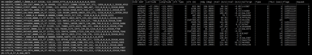
CSBee Protocol
CSBee (Comma Separated Bee values) is an information-rich plain text protocol based on the popular Aerobits CSV protocol, but with a number of additional fields. A PDF excerpt from the draft datasheet describing the CSBee protocol is included below.
Oversampling in PIO!
One of the issues that I’ve encountered repeatedly with decode performance has been that spurious noise can cause the PIO preamble detector or demodulator state machines to follow a stray edge into the wrong state, causing offsets in recovered clocks and garbled bits. After a few weeks of hard thinking, I convinced myself that it might be possible to refactor the PIO code to include oversampling (sampling the digital input signal from the data slicer circuit multiple times and then taking a majority-wins approach to classifying state of the pin as HI or LO). What followed was many days of PIO assembly hell and some rather difficult debugging, but I’m very happy to report that oversampling works, and seems to yield a significant improvement in both the integrity of detected preambles as well as the success rate at decoding Mode S messages! I neglected to get real numbers, but by John’s precision vibeometer I can confirm that the decode rate has improved by something like 2x-4x in most cases.

Inter-Processor Communication
To address the need for bidirectional communication between the RP2040 and ESP32, I implemented a custom SPI protocol. This took a bit longer than I anticipated, and was slightly over 1000 lines of code once everything was tested and working. The main complexities derived from communication being asymmetric (the RP2040 is the master and can talk whenever it likes, whereas the ESP32 is a slave and has to request communication explicitly from the master), and breaking large transactions into smaller 64-Byte chunks that could be easily handled by both the RP2040 and ESP32 without the need for huge buffers. The protocol is mostly going to be used for very frequent short communication between processors, as the RP2040 streams transponder packet information to the ESP32, but also must be able to handle medium sized data transfers (like sending over a few hundred byte large struct containing settings information) and larger data transfers (eventually, a full firmware image up to 16MB in size might need to be shuffled over SPI from the ESP32 to the RP2040 for an OTA update).
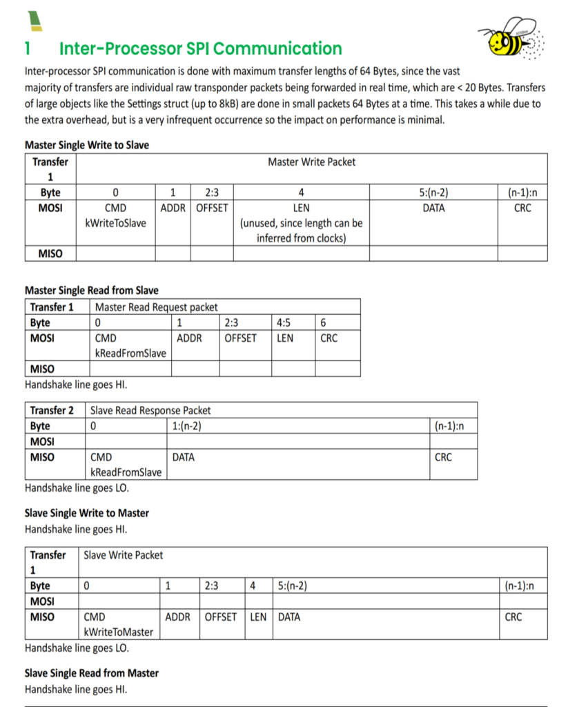
Initial tests seem to show the protocol working well! I’ve included a short GIF of transfers between the RP2040 and ESP32. Transfers shown in the GIF tested sending data with and without forced acknowledgements, writing and reading from a scratch register, and transferring large blocks of data that had to be broken into multiple messages.
🎉ADSBee Beta🎉
The primary factor gating the ADSBee Hardware Beta has been receiver performance. I didn’t want to send out units that I wasn’t sure that beta testers would be excited to use, and predictably, the majority of that boiled down to whether the ADSBee 1090 was good at receiving ADS-B and Mode S packets. Over the course of the last month, testing results have convinced me that the significant overhaul of receiver hardware in the transition from ADSBee 1090 Rev E to Rev F and the impactful improvements made to ADSBee decode logic have reached the performance targets necessary to begin manufacturing for the ADSBee Hardware Beta.
In my testing, while the ADSBee 1090 isn’t as sensitive as the best software defined radios that have dedicated pre-filters and LNAs targeted for use exclusively on 1090MHz, the ADSBee 1090 is approaching performance parity with extremely common unfiltered SDRs (like the RTL-SDR V3) and existing (much more expensive) embedded receivers like the uAvionix PingRx. I’m not yet done improving the decode logic, and I have a few more things in the pipeline that will hopefully improve receive performance further–but I’m convinced that Rev F hardware will be up to the task as-is for many of the applications that users have been excited about!
Performance comparison between an ADSBee 1090 and a uAvionix PingRX running off of the same antenna:
Performance comparison between an RTL-SDR v3 dongle and an ADSBee 1090 running off of the same antenna:


Phone screenshot from portable ADSBee 1090 testing outside of SFO:
OK that’s cool dude but when is the Beta?
Pre-orders for ADSBee Beta units will be opened soon, once I have solid quotes back from my contract manufacturer for Revision F of the PCBA. I expect pricing to be in the sub $85 range. All Beta units will include a 3D printed case, SMA antenna connector, WiFi antenna, and 1090MHz antenna. If manufacturing proceeds smoothly, the lead time for beta units will be about 1 month after preorders close.
In the meantime, I have a few hand-assembled units that will be made available to developers. If you are interested in contributing to firmware, please reach out to me on Discord and I’ll see about getting you some hardware!