
In this month’s loosely structured collection of words and punctuation:
- Open Sauce
- Hardware Shipment Updates
- Firmware updates
- 0.8.2
- John rants about MLAT
- John rants more about MLAT
- How to use MLAT with ADSBee
- UAT?
- Upcoming Events
🤖 Open has been Sauced!
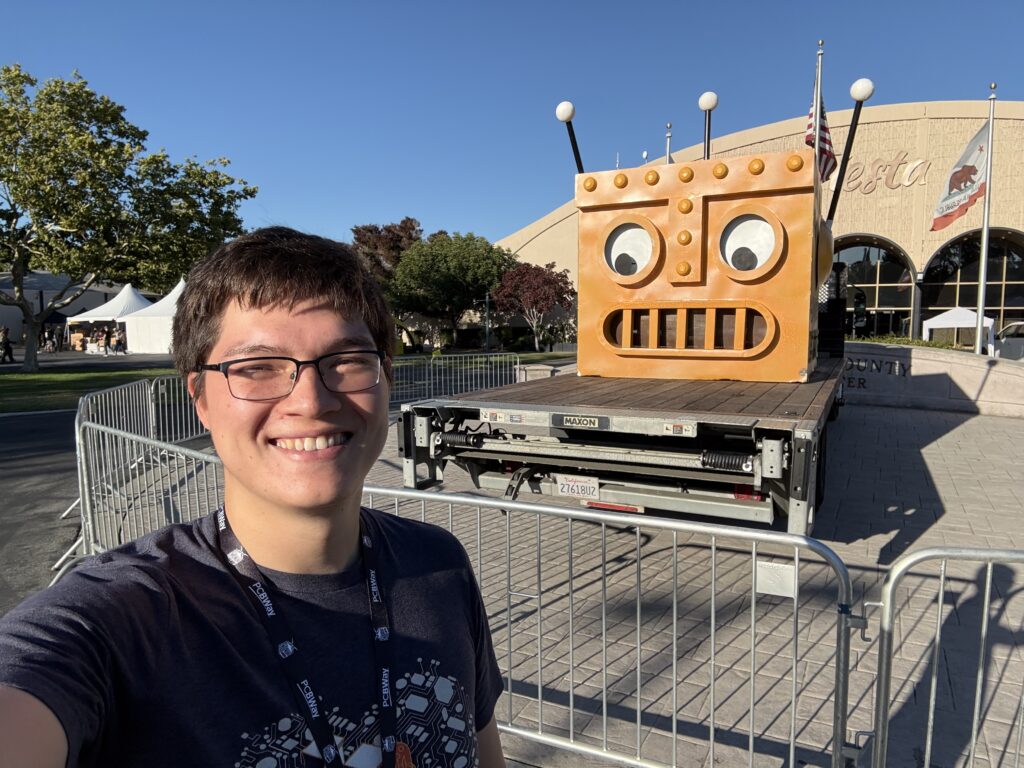
Open Sauce was an absolute blast! A whole lot of fun (and not much sleep) was had. An absolutely worthwhile annual adventure.
This year at the Open Sauce booth, we brought:
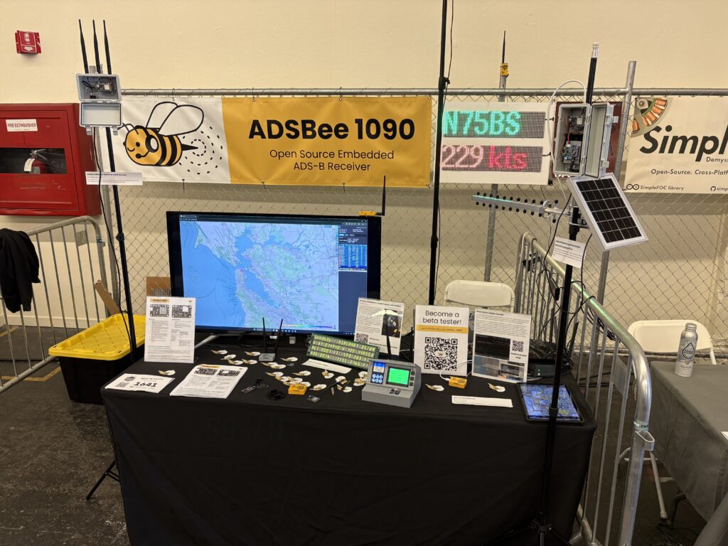
- A live demo of an ADSBee 1090U feeding tar1090 and a tablet running Avare via WiFi (lots of people also tried it out using Foreflight on their phones).
- A PoE ADSBee 1090U in a weatherproof pole-mounted enclosure.
- A battery-solar powered ADSBee 1090U equipped with a long range WiFi antenna (for feeding a wireless network from a remote location with better reception).
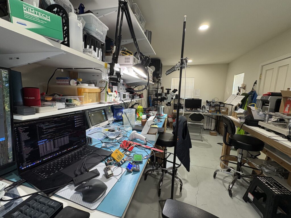
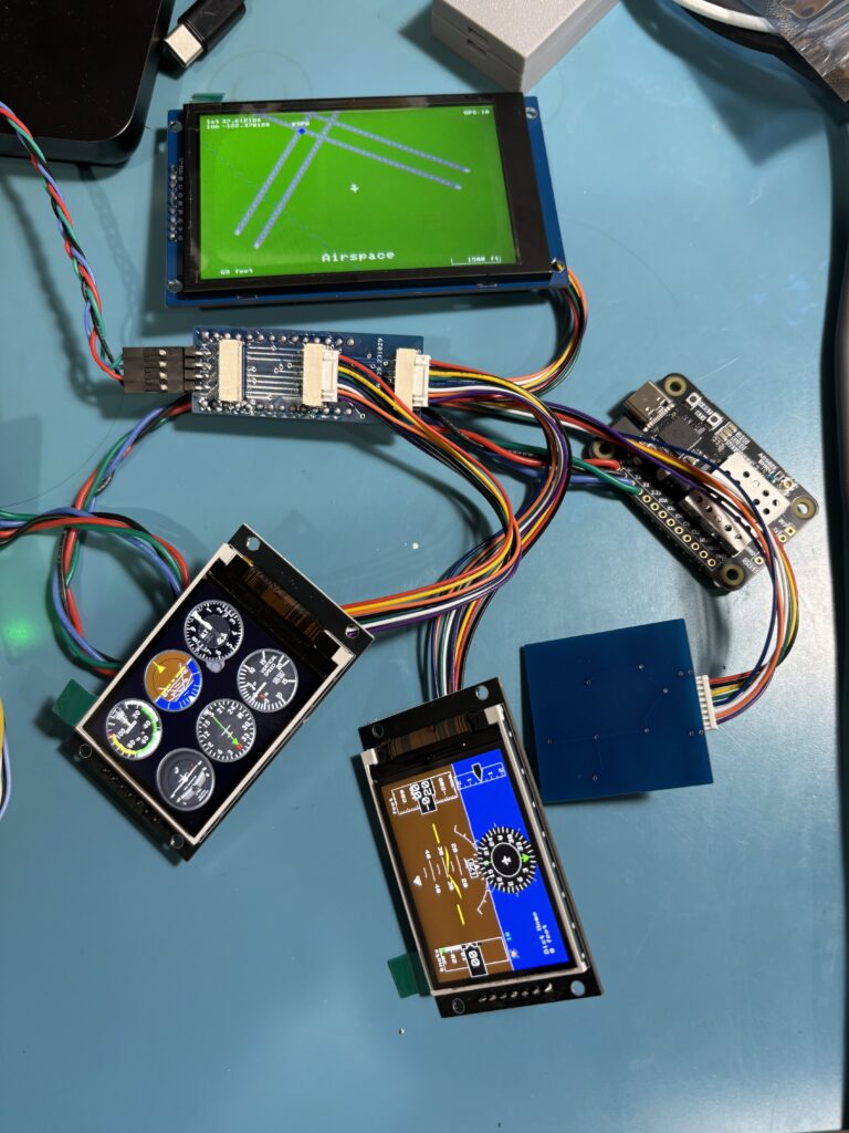
- A cockpit instrument panel mockup using displays from fpvtoys.net that showed live air traffic on an interactive moving map display (many thanks to Jeff Hendrix for heroically putting this together and integrating the ADSBee into his code in pretty much a single day after UPS lost its lunch).
- A custom-built 14-segment display listening to MAVLINK1 from an ADSBee 1090 and reporting statistics about aircraft in the area (courtesy of @evilwombat). We have had a few people ask about purchasing such a display–maybe if enough people pester him on Discord we can set something up 👀
- ADSBee m1090 and associated PCBA debris (fun petting zoo vibe).
- Bigge WS2812 display showing aircraft stats from an ADSBee 1090 (also reported over MAVLINK1, also by our excellent friend @evilwombat).
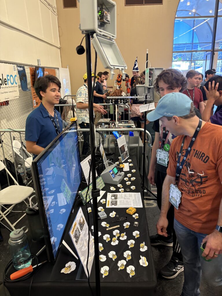
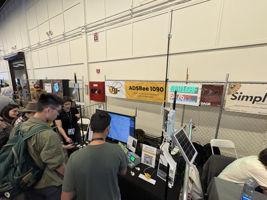

To those of you who heard about the project for the first time at Open Sauce, and decided to tag along–welcome! We’re very happy to have you.
Also, we got a shoutout from Jeff Geerling! I highly recommend watching his vlogs from Open Sauce to get an idea of just how nuts the event was.
📦 Hardware is Shipping!
ADSBee 1090U Preorders are 100% shipped, and new orders are being fulfilled in 1-2 days! We’ve been sending packages across the US and across the world, and I’m excited for everyone to begin turning on their new receivers.
The ADSBee PoE Pant went live and has since sold out, but I’m working on getting more back in stock (the initial stock was a relatively small supply of prototypes–I’m gearing up for a proper manufacturing run this month). Fortunately, we still have an ample supply of ADSBee 1090Us and the necessary antennas to make things go, and I’m going to try my best to line up subsequent production runs such that we don’t encounter any unexpected stock shortages.
💾 Firmware Updates
This month marked the release of firmware version 0.8.0 (and two subsequent patch releases, bringing the latest firmware version to 0.8.2). This new firmware update includes a hefty refactor of the SPI coprocessor communication system, providing vastly improved interprocessor communication reliability, and also makes a number of smaller usability improvements:
- 1090 LED blinks in regular patterns to indicate that the RP2040 is updating firmware on other processors: triple blinks for updating the CC1312, and double blinks for updating the ESP32.
- TCP keepalive is added to Mode S Beast feeds to improve reliability on some networks when surrounding air traffic is sparse.
- OTA update speed and reliability improved.
- Max number of feeds increased to 10.
- Filter added to remove duplicate Mode S messages caught by multiple demodulator state machines simultaneously (this causes a slight reduction in the packets received metric, but it’s reflecting a more accurate value now).
- Core network settings added so that ADSBees running on Ethernet don’t get reverted to running on WiFi after a firmware update to a new version (this hasn’t yet been tested extensively, so keep your ladder handy when updating to the next firmware version that rolls the settings version).
- 🎉🎉 MLAT-capable timestamps!!! 🎉🎉
All new ADSBee 1090Us are currently shipping with firmware version 0.8.2. If you got an ADSBee 1090U from the beginning of the preorder batch, it may be flashed with 0.8.0 or 0.8.1–I recommend doing a quick firmware update before diving in!
⏰ Wait what’s the big deal with MLAT
If I seem a little bit excited about MLAT timestamps, it’s because I’m a LOT excited about MLAT timestamps! What I thought would be a quick bug fix turned into a massive week-long side quest (with excellent support from @wiedehopf). Long story short, ADSBee is now very good at counting time, with a resolution of just over 2 nanoseconds. This makes its timestamps accurate enough that they can be used to triangulate aircraft positions. Exciting!!
If you’re interested in learning more, or want to learn how the sausage is made, read on!
🌭 MLAT Timestamps and how ADSBee uses cursed DMA + PWM peripheral + SysTick timer hackery to make them less wiggly
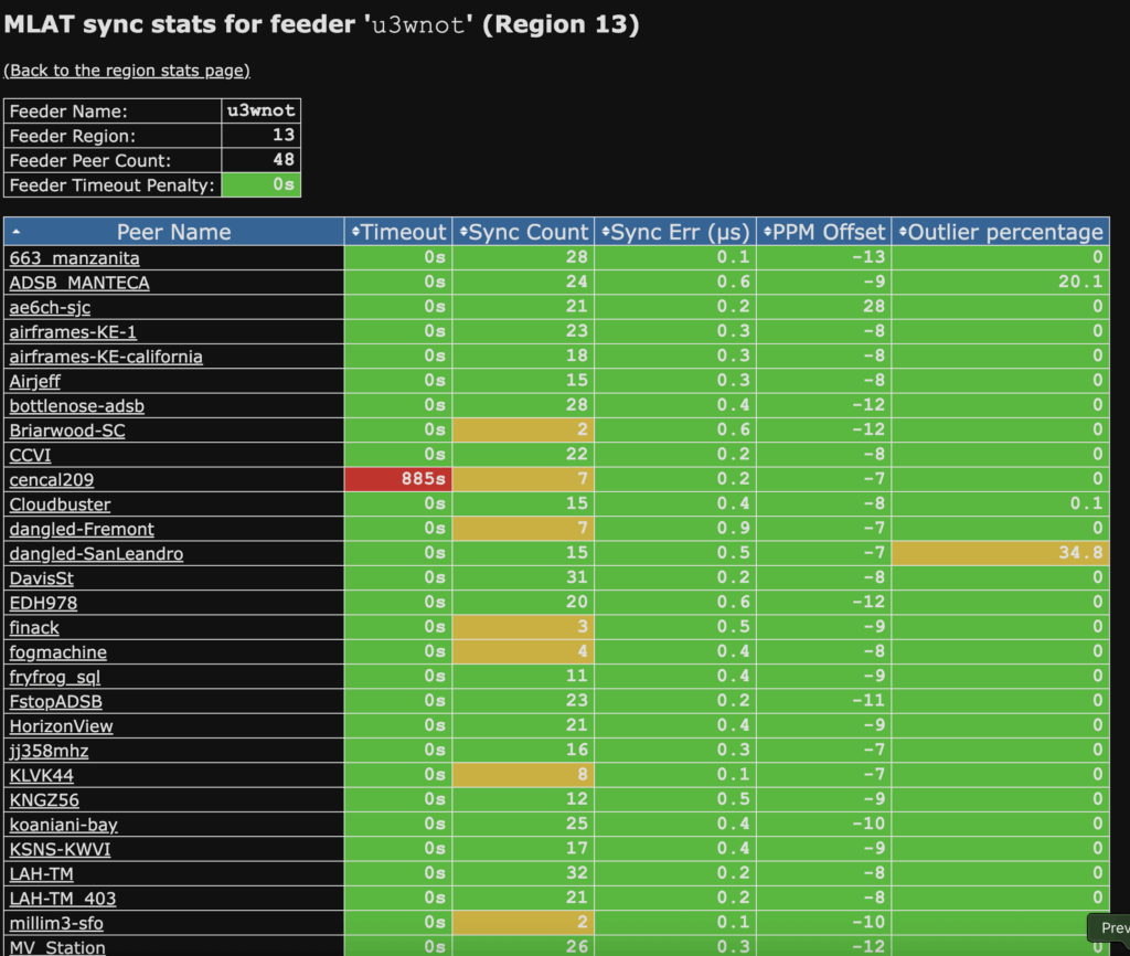
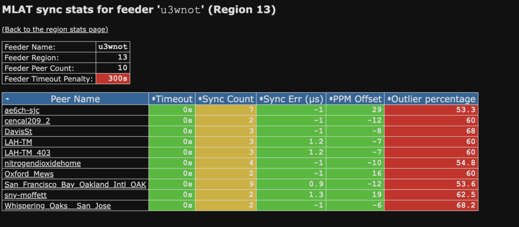
One of the lesser known uses of an ADS-B receiver is multi-lateration, or MLAT. Multiple receivers in different locations on the ground can receive a packet from an aircraft simultaneously. With knowledge of each receiver’s location, and a relative timestamp when each device received the packet from the aircraft, an MLAT server can determine the exact location of the aircraft when it transmitted the packet. This is quite useful in a number of scenarios, since not every packet that an aircraft transmits contains its location, and some aircraft don’t transmit their location at all (e.g. military aircraft). By synchronizing the reception of any valid Mode S packet transmitted by these aircraft, we can decipher their locations, and can often do so with higher resolution than we could with ADS-B locations alone, since ADS-B location normally only updates at around 2Hz, assuming every position packet is received successfully.
Thanks to the work of a number of open source contributors over the years, there exists a robust network of ground-based ADS-B receivers already being used for MLAT around the world. In order to join this MLAT receiver network, an ADS-B receiver needs to speak a specialized mlat-client protocol, and also needs to be able to provide a data stream of received packets with a associated relative timestamp for each packet. The relative timestamp takes the form of a 64-bit 12MHz counter value (ADSBee uses a 48Mhz counter, but this gets divided down to provide a 12MHz value to the MLAT server). Its absolute starting point (e.g. what time corresponds to a timer value of 0) is unimportant, since the MLAT server can “zero” the timestamp across multiple receivers when they receive a packet from the same aircraft. However, the counter must increment with consistent timing (ie. There can’t be any “jitter” in how long one tick of the timer takes), as this would defeat the receiver’s ability to accurately determine the range of an aircraft based on time of flight duration. This jitter requirement is rather strict; since the speed of light is 3e8 m/s, we can see that an uncertainty of 1us in the timestamp of a packet would lead to a range uncertainty of 1e-6 s * 3e8 m/s = 300 m! This kind of sensitivity to even the slightest timestamp uncertainty means that many of the simpler approaches to capturing a timestamp on an embedded device, such as using an interrupt to read a timer, are not workable solutions for capturing an MLAT timestamp. For instance, interrupts on the RP2040, even running directly from RAM, can have a timing uncertainty of around half a microsecond to multiple microseconds, depending on their priority and when they are triggered.
On the ADSBee, there were a few challenges encountered on the path to generating a 48MHz timer capable of capturing relative timestamps of incoming packets from the PIO peripheral with low jitter. The first was the challenge of synthesizing the timer itself. The RP2040 only has one 64-bit hardware timer, which is used for the global microsecond timebase. Given that this microsecond timer is used for all kinds of tasks throughout the code, it seemed unwise to repurpose it to run at a higher clock rate. Alternatively, there is a watchdog timer, which is also used by the firmware for important things, and a few other hardware timers which also lack the depth to capture a full 64-bit count. Fortunately, an ADSBee contributor (@gwoplock) noticed that the RP2040 has one unused SysTick timer per core, which includes a fractional clock divider that can be set to provide a custom clock rate. Earlier this year, with some debugging help from another contributor @wiedehopf (who also happens to be the maintainer for the most popular open-source ADS-B decoders and MLAT software), I was able to get this unused SysTick timer configured as a 48MHz counter with 24-bit width, and added an interrupt to count the number of timer wraps in order to fill in the remaining 40 bits required for a 64-bit timer. At 48MHz, a 24-bit timer doesn’t last very long, so wraps occur every 0.134 seconds or so—but by setting the interrupt priority of the timer wrap counter Interrupt Service Routine (ISR) to be higher than other interrupts, I can effectively avoid an interrupt reading the timer when it has a pending wrap that hasn’t been counted.
With the 48MHz counter synthesized via the SysTick timer and a custom ISR, the task of assigning a timestamp to each incoming decoded packet remained. I originally tried the smooth brain approach of simply reading the 48MHz counter inside the ISR that triggered at the beginning of a demodulation, when the preamble detector PIO kicks off its adjacent demodulator PIO state machine, but the jitter in this interrupt timing proved to be too severe. Minute timing variations of a fraction of a microsecond between the moment the preamble was detected to the moment the MLAT timer was read caused my timestamps to “jitter” by enough that the MLAT server was unable to get a good synchronization between my ADSBee test receivers and adjacent receivers in the same area (many thanks to @wiedehopf for helping me set up tests for this step)!
I knew that I needed some way to read the 48MHz MLAT counter in a deterministic manner that would not be affected by the variable latency of interrupt execution on the RP2040. Most web searches for similar questions regarding edge timing suggested using PIO blocks, but all of the PIO blocks on the RP2040 were already utilized as preamble detectors or demodulators or associated machinery. Other suggestions mentioned using DMA, but after some initial excitement I was disappointed to learn that the SysTick timer used for the 48MHz counter was specific to each processor core, and was not accessible to the DMA peripheral.
My thinking wandered to the PWM peripherals on the RP2040 that can be utilized as timers. On other families of microcontrollers, hardware timers can be used to capture the timing of a rising edge on GPIO. If I could repurpose a PWM peripheral as a timer that started counting the moment a message preamble was matched (by triggering on the same GPIO rising edge used to trigger a PIO demodulator), I could then read that timer value in my ISR that fired at the beginning of message demodulation to effectively de-jitter my 48MHz packet timestamp! The packet timestamp would just need to be the 48MHz counter value read in the ISR, minus the value of the PWM counter, which started counting up from 0 at 48Mhz when the demodulation interval began (and before the ISR had a chance to fire). The depth of a PWM timer was only 16 bits, but given that the demodulation begin ISR was expected to fire within a few microseconds of the timer beginning to count, I would not need to worry about overflow before the timer counter would be read.
Tragically, upon closer examination of the layout of the RP2040 PWM peripherals, I realized that I would not be able to assign a separate PWM timer to each of the GPIOs used for triggering demodulation PIOs. Each of the PWM timers has only a handful of pins that can be used as triggers, and adjacent pins are often assigned to the same PWM timer. The specific layout of the ADSBee PCB would require three adjacent pins to each trigger different PWM timers, which would sadly not be in the cards for the RP2040.
After this latest setback, I returned to the drawing board once again, and ended up with a harebrained scheme that quickly emerged as the only remaining viable option that I could think of. A 16-bit PWM timer counts continuously at 48MHz, and a DMA channel captures its value upon the beginning of a demodulation interval. This DMA channel is triggered via PIO using a FIFO pull command slotted into the demodulator state machine’s digital oversampling code, since it was the last remaining place I could fit an extra instruction in the PIO logic (only 32 instructions are allowed per PIO block, and I’ve used absolutely all of them). When the demodulation begin interrupt fires, the interrupt service routine reads the value of the same PWM timer, and then subtracts the value captured by the DMA channel in order to create a 16-bit “jitter correction” value. This jitter correction value is then subtracted from the value of the 48MHz MLAT timer, as read from within the demod begin ISR. Each of the three preamble detector / demodulator state machine pairs has its own DMA channel dedicated to capturing the PWM timer timestamp on demod begin, so no DMA PWM timer captures end up stepping on top of other PWM timer captures. Simultaneous execution of demod begin ISRs also isn’t an issue unless one ISR is stalled for longer than about 1.3ms (the time it takes the 16-bit PWM timer to roll over).
With some luck, it worked! Voila, 48Mhz de-jittered MLAT timestamps on the RP2040! No FPGA or continuous sampling code required.
I’m quite excited about the long-term prospects of utilizing 48MHz timestamps on the ADSBee for MLAT purposes. Using a higher frequency sampling clock than most SDRs (which timestamp around 12MHz) should in theory allow ADSBees to get better range accuracy, which in turn means that MLAT receiver arrays could be concentrated into smaller areas than might otherwise be required. I’m particularly interested in the possibilities around integrating MLAT timestamping with Pulse Per Second (PPS) and position outputs from GNSS receivers, which could allow clusters of ADSBees (fixed or on the move) to provide MLAT demodulation capability to a networked server receiving all of their datastreams. Cracking the high resolution, low-jitter timestamp problem opens a new horizon of possibilities for ADSBee, and I’m excited to see where the road goes next!
📈 How can I use ADSBee for MLAT?
ADSBee can’t feed MLAT data on its own, because it’s (currently) too dumb to understand how to compress files in gzip format, a quirk of the JSON-based protocols that the open source MLAT servers use. In order to feed MLAT, you’ll want to spin up an ultrafeeder docker container and use that to run the actual mlat-client software. The side benefit of this is that you get a cool local tar1090 map, and can feed even more websites than you could with the ADSBee alone, without worrying about bogging down the ESP32. There’s an example docker compose here, but you’ll want to at least change the MLAT_USER field so that you don’t steal the UID of my test device.
🛩️ UAT when?
UAT firmware is coming! It’s currently in development and should be released in the next few weeks. Join the discord if you’re interested in trying it first!
📅 Upcoming Events
The ADSBee team will be at two more events this year!
Commercial UAV Expo (September 2-4, Las Vegas)
(Pssst, contact me on Discord if you want a free ticket to CUAV expo. They made me pay a lot of money but at least I can give out free tickets.)