I’ve been working hard on ADSBee 1090 since the July update. Here’s what I’ve been up to since y’all last heard from me!
TL; DR Redesigned the analog and RF frontend of the ADSBee 1090, new rev with cool features (ADSBee 1090 Rev F) coming soon. Also, lots of firmware work! Hardware beta details still TBD pending bringup of the new rev.
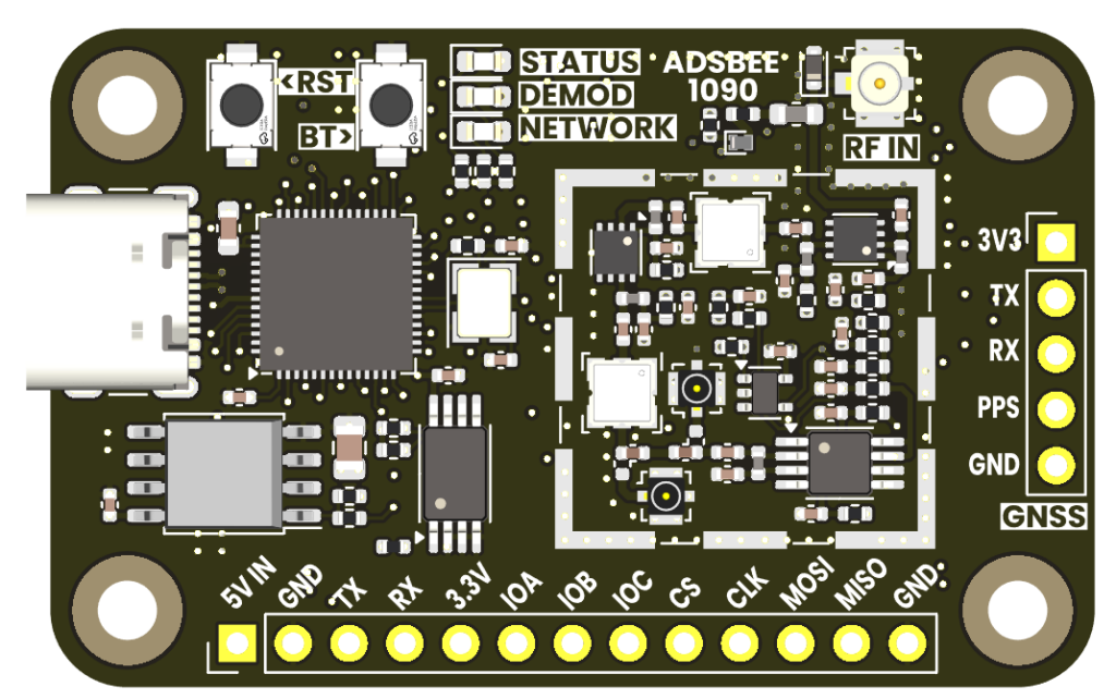
Testing ADSBee 1090 Rev E
In late July, I took some ADSBee 1090 Rev E PCBAs with me on a trip, and had a grand time collecting aircraft contacts and adding features to the RP2040 firmware. Important additions include bringup of our new 64kbit EEPROM (which should be large enough to store any feeder IP addresses, WiFi passwords, etc. that we might need), addition of Mode S Beast protocol as serial output, and implementation of a high resolution 12MHz timer for multilateration (with wonderful assistance from one of our community members, @gwoplock).
During the course of the trip, I was able to demonstrate some rather long range contacts even with a relatively primitive base station setup, but I did notice that the receiver performance suffered when aircraft were too close to the receiver. Once I got back home, I started some relatively squishy / qualitative benchmarking against a few software defined radio dongles and an off-the-shelf FPGA-based receiver (uAvionix PingRx). While the results weren’t very precise, it became apparent that some improvements to the ADSBee 1090’s receive performance would be necessary for the device to be a competitive solution. After a few weeks of using ADSBee 1090 Rev E, it was also clear that there were a few too many knobs that required fiddling from the user (receive gain adjustment, positive and negative trigger thresholds), which indicated unnecessary complexity and room for improvement in the UX. Thus began a few weeks of some pretty aggressive redesign of the RF frontend and analog circuitry on the ADSBee 1090, culminating in releasing ADSBee 1090 Rev F to manufacturing yesterday (2024-08-17).
Analog Redesign
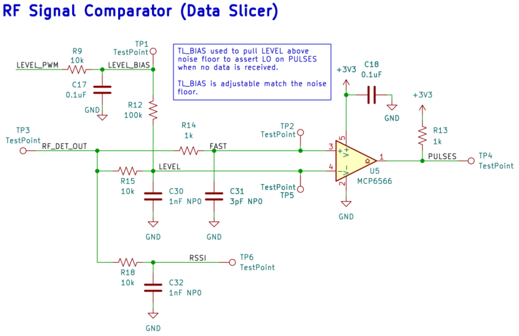
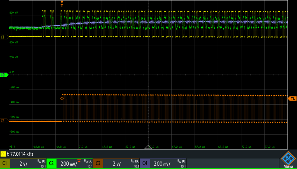
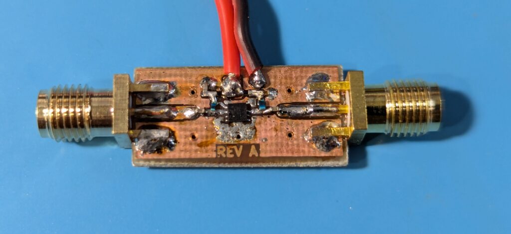
Analog circuitry redesign consisted of etching some teeny tiny PCBs (bodge boards) in my garage with room for a few analog components, then VHBing the bodge board onto the back of an ADSBee 1090 and tapping into the circuit via test points or pads on the front of the board. I iterated through four separate analog designs before I finally settled on a relatively popular topology called a Data Slicer (commonly used for decoding an AC Manchester coded signal with some level of DC bias). This topology has the side benefit of removing an op amp and analog switch from the circuit, which frees up space and BOM cost for RF frontend improvements.


The final design no longer requires a user to set receive gain and two trigger thresholds, since it automatically adjusts to fit the signal amplitude of aircraft at various ranges, and only requires a single adjustable DC bias that can be set to properly ignore the noise floor. My hope is that most users will never have to change this value, which will be set to a reasonable default in firmware, and may only need to adjust it if they are doing some advanced maneuvers before the ADSBee 1090’s RF input, like adding a cavity filter or an additional Low Noise Amplifier (LNA).
RF Redesign
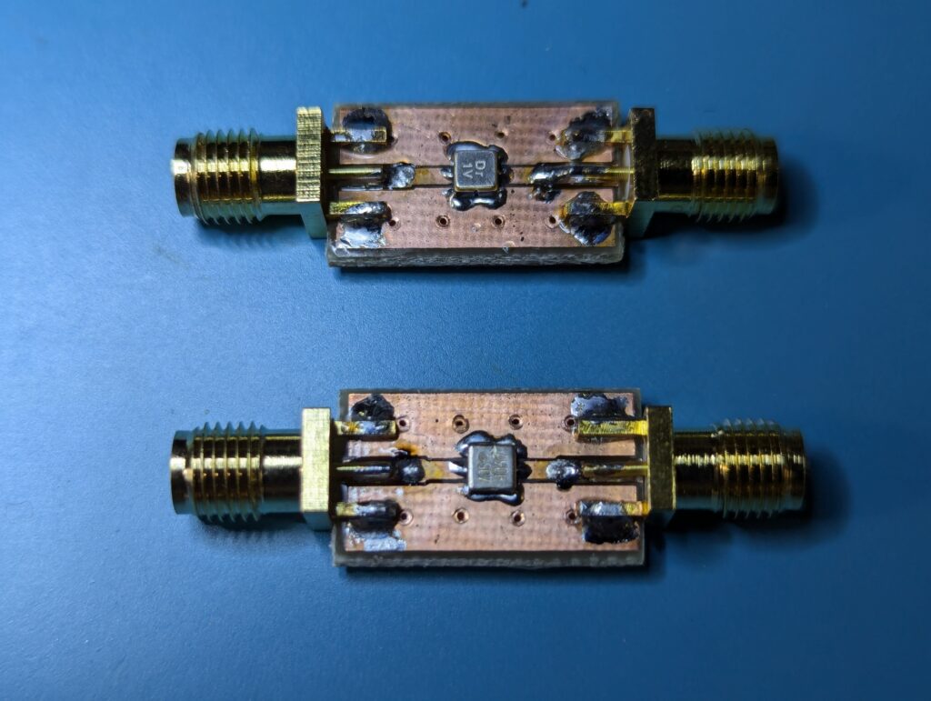
Poking and prodding at the ADSBee 1090 Rev E circuit has indicated that range for the ADSBee 1090 can be significantly improved through an additional LNA gain stage. I etched a PCB to allow the addition of said gain stage using the same LNA part number as already exists on the ADSBee 1090 (Berex BLB01), and also evaluated performance with an off-the-shelf LNA. Both LNAs yielded a significant increase in number of aircraft tracked, so I’m excited to see what end to end performance looks like with a properly integrated dual gain stage RF frontend.
In addition, I etched some test boards for qualifying an alternative SAW filter from another manufacturer that promised similar performance characteristics with slightly lower insertion loss. Through some supply chain finagling, I’ve been able to get pricing for SAW filter components down from ~$15 each at 100x quantity (crazy, absurd, absolutely wild) to the $1 range. If people are interested in some 1090MHz SAW filter boards (just the filter and some connectors, nothing else), shoot me a message on Discord or via email and I can look at cooking up a group buy of some properly laid out and enclosed filter PCBAs.
ADSBee Rev F’s RF frontend includes a number of the goodies above, with two cascaded LNA and SAW filter stages. I’ve also moved the first SAW filter stage behind the first LNA stage in an attempt to improve SNR in typical environments. This means that if you’re in a really, really noisy environment or have a relatively wideband antenna, you might need an additional filter in front of ADSBee 1090, but I think this will be a relatively rare occurrence.
I also added test ports to enable proper characterization of gain and noise factor of the ADSBee 1090’s RF signal chain, as well as characterization of the narrowband input match on the AD8313. This will hopefully allow me to flesh out any gremlins that might still be hiding in the RF frontend and hindering receiver performance.
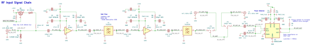
Lastly, a switchable bias tee circuit (3.3V out, 200mA) was added to the RF input to allow the ADSBee 1090 to power an external LNA before its first stage, if so desired. I don’t anticipate many users needing this feature, but for now, it’s there if someone wants it!
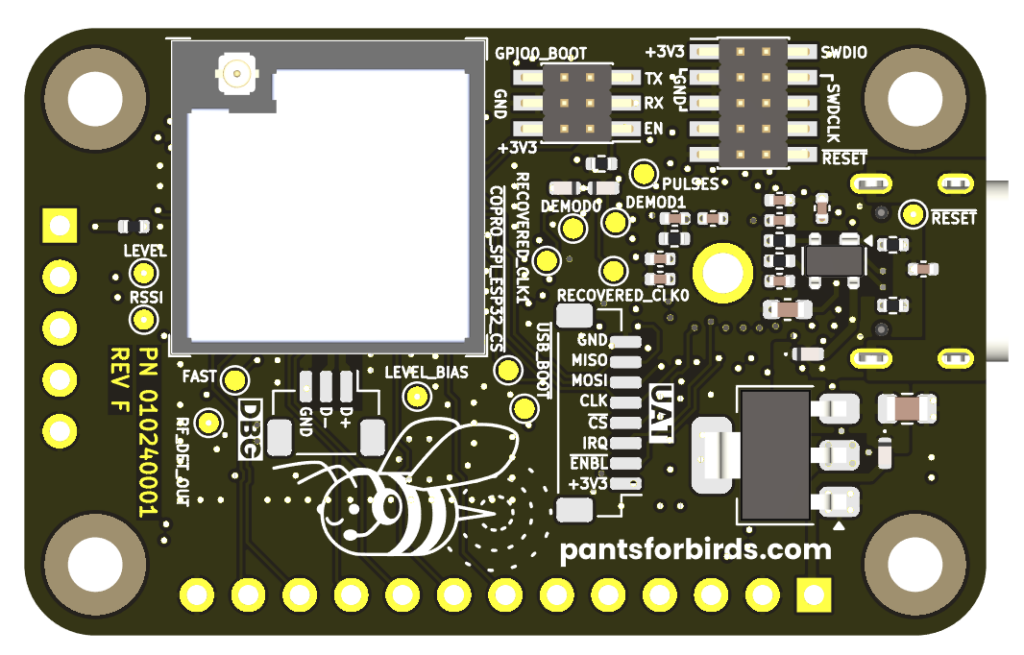
ADSBee 1090 Rev F
Here it is! Rev F looks pretty similar to Rev E on the surface, but includes the following improvements:
- Overhauled analog circuitry with a design that automatically adjusts sensitivity to different transmit power levels. This should hopefully remove the “doughnut effect” we were seeing on Rev E, which made the receiver only sensitive to aircraft in a relatively narrow band of radial distances. The new circuit uses fewer expensive components (no op amp or analog switches), so this BOM cost and board space savings has been reinvested into improvements to the RF frontend.
- Moved to a two-stage amplifier with double SAW filters. Added MHF3 connectors for characterizing noise figure of the RF input stage and characterizing the narrowband impedance match of the AD8313. I’m hopeful that we can improve our signal to noise ratio by a few dB here.
- Provisions for utilizing 2x PIO state machines as interleaved demodulators. In theory this could let us keep scanning for preambles even in the midst of decoding a message.
- Fixed an ESP32 SPI trace issue that was causing crashes (SPI lines were previously shared with ESP32 internal flash memory).
- Added ESP32 JTAG USB connector.
- Switchable bias tee for external LNA.
- JST-SH connector footprint for connecting to another board via the coprocessor SPI bus plus a few GPIOs. The hope is to use this for development of a UAT receiver add-on at some point down the road.
- Switching the EMI can to a two-piece design that allows the cover to be removed and replaced without desoldering anything.
I’m excited to get my hands on a few of these boards to see what they can do. Feel free to follow the adventure on Discord, or check in for an update next month! If Rev F proves itself Worthy, the ADSBee Hardware Beta will kick into drive in earnest. Thank you to all of our (very patient) Beta testers!
If you’d like to join the mailing list for the Hardware Beta (if you got this update as an email, you’re already on it), feel free to sign up here.