- Cheap Mode S test signal source
- Hardware
- ADSBee 1090U on backorder
- ADSBee m1090 on backorder
- Firmware
- New RC’s!
- Dynamic range improvements
- Altitude decoding fixes
- Whereplane
📶 Building a Mode S Transponder for < $40
Disclaimer: Don’t do this unless you know what you’re doing, and absolutely don’t stick an antenna onto the test signal source I’m about to describe. Test signal sources are intended for low power use in a controlled environment only, so that they don’t interfere with legitimate transmissions and land you in legal trouble.
When building an ADS-B receiver, it can be helpful to have a low power Mode S signal source available to test with. There are many accounts of building Mode S test signal sources out of transmit-capable software defined radios (SDRs) like the HackRF. These fit the bill for a variety of use cases, ranging from legitimate purposes like Mode S receiver R&D to drawing JD Vance over Mar-a-lago.
SDRs are capable of a lot more than basic Mode S modulation, but this additional capability comes with quite a bit of overhead. Instead of the simple on/off pulse keying pattern used by Mode S, SDRs read from a buffer of I/Q samples, which represent the magnitudes of in-phase (I) and quadrature (Q) RF signals that are mixed to form an output signal. By varying the amplitude of these two signals (think a sine wave for I, and a sine wave phase shifted by 90 degrees for Q) and combining them, the SDR can generate just about any arbitrary RF waveform, limited only by the rate at which it can consume new samples and physical limitations of its hardware. With a high enough sample rate, and capable frontend hardware, SDRs can mimic extremely advanced waveforms like WiFi and LTE, which transmit across a wide frequency range (bandwidth) simultaneously.
The extra capability of transmit-capable SDRs comes with a cost. Usually, they need a companion computer like a laptop or Raspberry Pi to feed them with samples, and if you’re storing a few seconds or minutes of messages with a high sample rate, the size of the I/Q files being stored then streamed to the SDRs can get quite big (Gigabytes). Of course, there’s also the monetary cost of the SDR itself! The HackRF runs about $340, and prices generally go up from there.
In the spirit of the ADSBee, which uses a Pi Pico’s PIO peripheral to receive Mode S messages, I figured that it wouldn’t be that hard to make a device that transmits Mode S messages using RP2040 PIO and some basic RF hardware. As a plus, I would have a great deal of control over the actual waveforms I was transmitting, since the RP2040 can have its PIO run at up to 200MHz (if you up the system clock rate to 200MHz), and could build a very simple low-bandwidth interface for transmitting packets, where instead of sending a big blob of IQ samples to the test transmitter I could simply send the contents of the packet I wanted to transmit.
Mode S uses on-off keying, so the only necessary parts are some kind of RF signal source that could generate out 1090MHz signal, and a way of modulating that signal on and off very quickly (to form the 1MHz Manchester coded pulse stream used to encode the message).
RF signal sources can be found pretty readily in the form of VCOs (Voltage Controlled Oscillators) which can be integrated into PLLs (Phase Locked Loops) that multiply a reference signal from a crystal oscillator (e.g. 25MHz) into a higher frequency RF signal (e.g. the 1090MHz carrier used for Mode S). After some hunting on Amazon, I found an inexpensive PLL dev board for $23 using an ADF4351 PLL that I managed to get working well for synthesizing my 1090MHz signal. The AD4351 receives configuration commands over SPI, which was easy to set up via the Pi Pico. It did take some tuning of various parameters to get the PLL stable, but it seems to work pretty well for the most part, and a digital lock signal can be used to restart the PLL whenever it loses lock.
Keying RF signal sources on and off can be done, in its simplest form, by an RF switch. Some more Amazon scrounging yielded an HMC349 RF switch def board for just $14, which I hooked up to a digital output from the RP240 PIO peripheral to enable my on-off keying for sending messages.
The dirt simple block diagram of a minimal Mode S Transponder looks something like this:
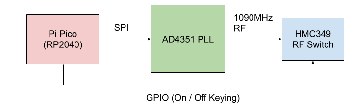
So, there you have it! A Mode S test signal source for less than $40. Note that calling this a full “Mode S Transponder” is a bit clickbait-ey, since a fully featured transponder needs to be able to receive BPSK (binary phase shift-keyed) secondary surveillance uplink messages on 1030MHz, which is quite a bit more complicated. Maybe we will come back to that another time! For the time being, this simple signal source has been more than enough to provide a number of valuable insights while testing ADSBee.
I extended the functionality of the basic Mode S test signal device by adding a series of switchable PE4302 attenuators to the output, allowing me to set a variable 93dB of attenuation on the transponder output. This was critical for testing ADSBee’s dynamic range (more on that later), with the ability to generate a series of transponder messages at a wide range or power levels, to simulate aircraft both close by and far away.
Here’s what the actual build looks like! I 3D printed a big base plate to stick everything to, and used a cursed combination of wire wrap, crimped ferrules, and Dupont pin headers to wire everything together. Note that the RF switch is SPDT; when the switch is “closed”, the RF signal flows into the series of 3 step attenuators. When the switch is “open”, the RF signal flows to a 50 Ohm terminator to minimize reflections.
Even though the RF signal power coming from this test fixture is pretty low (+5dBm), and I never connect it to any antennas, the radiated emissions from the open PCB transmission lines and possibly suspect RF terminations is enough to trigger some of my more sensitive ADSB receivers when they are nearby. This rig definitely needs some shielding (and/or or less exposed PCB layout) for use in an unshielded environment.
If you’re curious about the BOM for this build, I’ve included some links below. Firmware and schematics aren’t provided, because, well, if you know what you’re doing with this you probably can figure those out pretty quickly yourself (and I don’t want to be in the business of distributing schematics for non-certified Mode S transponders that people could use to get in trouble).
- Pi Pico: 1x $5
- ADF4351 PLL: 1x $23/ea (Note: this isn’t the exact one I used, since that one is no longer stocked. Beware the ADF4350 PLL’s, I wasn’t able to get one of those to work for some reason, they may have a busted layout).
- HMC349 RF Switch: 1x $14/ea
- PE4302 RF attenuator: 3x $15/ea
⚙️ Hardware Updates
At the time of this writing, both the ADSBee 1090U and ADSBee m1090 are sold out and on backorder. We expect another batch of ADSBee 1090U’s to land around the end of this month, and a batch of ADSBee m1090’s to land sometime early to mid April.
Backorders are first come first serve, so it doesn’t hurt to place an order in the meantime!
We still have GS3M PoE’s (industrial ground station receiver), as well as ADSBee m1090 Eval kits in stock.
💾 Firmware Updates
0.9.0-RC13
Firmware version 0.9.0-RC13 fixes some bugs discovered and corrected by community members related to UAT downlink messages being forwarded without proper Forward Error Correction applied. Packets were being corrected on-device, but then forwarded in their uncorrected form, leading to some aircraft showing up with garbled callsigns or incorrect altitude as they got further from the receiver! Thank you to @justin4046 for his work on this issue.
This update also fixes some Mode S Beast feeds where ADSBee wasn’t sending its unique base station ID (UUID) at the start of the feed, causing online exchanges like airplanes.live to assign receivers a randomly generated UUID. This bug was only present in some Mode S Beast feed modes–if you notice that your map is missing from an aggregator after updating your firmware, double check your UUID to see whether it’s been changed to the UUID stored for that particular feed on your device! Thank you to @justin4046 for submitting a fix to this issue.
Signal strength and signal quality were added to each aircraft report over CSBee; these values were being received before, but weren’t yet stored in the aircraft dictionary or correctly printed in CSBee messages.
For developers’ convenience, a build script was added to the repo to build firmware images for all three processors. Thanks @pitchlinkaero!
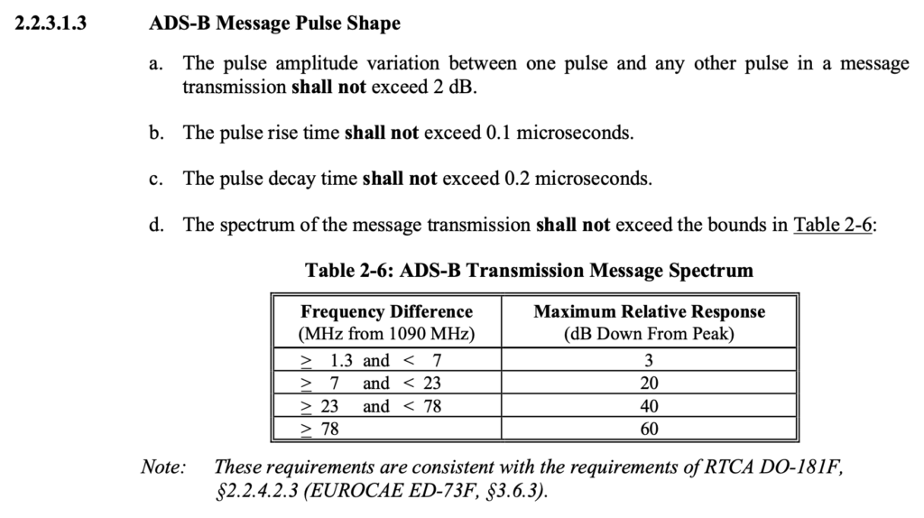
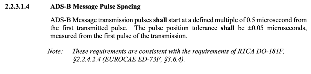
Last but certainly not least, RC13 includes a full re-write of the PIO preamble detector and demodulator code to further improve dynamic range across a variety of pulse shapes permitted by the DO-260C standard (Mode S transponder minimum operational performance specifications). While most aircraft use pulses with just a few ns of rise / fall time, the actual transponder spec does permit rise times as slow as 100ns and fall times as slow as 200ns.
The previous implementation of the ADSBee preamble detector had a pretty hard time with wider pulse shapes, since they interacted with the non-symmetric rise / fall behavior of the AD8313 power detector in the ADSBee’s RF frontend. I added custom pulse shape adjustments to the PIO code in the Mode S test fixture, and was able to perform sweeps at a variety of power levels and pulse shapes to see how the ADSBee fared, using proportion of packets received as a performance metric.
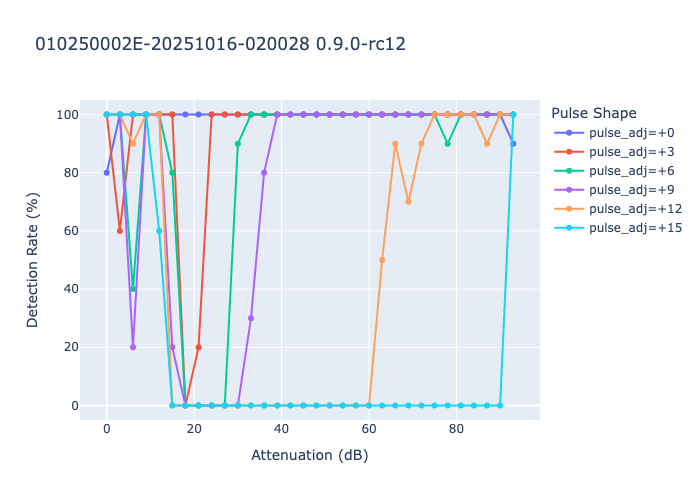
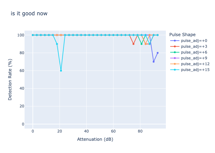
The plot below shows performance with RC12 firmware. Each +1 of the pulse_adj parameter corresponds to a widening of each pulse by 16ns, and the attenuation parameter refers to the amount of attenuation applied to the +5dBm RF signal coming from the test fixture’s signal generator. We can see that wide pulse shapes (240ns additional pulse width) drop out even for low powered signals around -85dBm, while narrower pulse shapes fare better until around -15dBm or so.
After some significant re-writing of the preamble detector and demodulator (including some clever hacks), performance was significantly improved, with excellent performance across 90dB of dynamic range for most pulse shapes.
The particular changes used to achieve this include changing the demodulator from a dynamic clock recovery algorithm to a fixed sampling routine (made possible since the cumulative pulse position error is relatively tight according to the DO-260C spec).
Another hack was the introduction of a unique “clock stretching” algorithm that delays sample timing based on the RSSI of the preamble (the AD8313 has a much slower fall than rise time, meaning it’s best to sample later in the bit period for high power messages, since the slow fall time causes troughs between pulses to lag in phase and narrow as receive power increases). This clock stretching is achieved by sampling at a fixed interval after each expected positive pulse in the preamble. If the sample reads high, we can assume that the signal power is high enough that we’re still in the extended fall time of the pulse coming from the AD8313. This stretch is repeated for each pulse in the preamble (4 total), providing four “steps” of phase lag that can be applied to the subsequent sampling timing dependent on the power of the incoming transmission. This may reduce the accuracy of MLAT timing, since higher power messages get their sampling start time delayed by some number of nanoseconds compared to low power messages, but we could calibrate this out after the fact by changing MLAT timer values based on recorded message RSSI if it does indeed become a problem.
I’m excited to hear about results from the field with these dynamic range improvements! The optimizations to the PIO programming were carefully balanced to improve dynamic range on the test fixture while also keeping receive performance on an actual antenna (with real planes in the air around the receiver) relatively equivalent to the past firmware.
0.9.0-RC14
Firmware version RC14 fixes an ADC configuration bug that was introduced in RC13, which was causing RP2040 MCU temperature values to read too high, and also fixes a bug in the Mode S decoder that caused some aircraft to report incorrect altitudes when they sent a particular format of Airborne Position message that utilized Gillham-coded altitude values, as well as some other miscellaneous bug fixes. If you are using an ADSBee with local position decoding (e.g. displaying air traffic via MAVLINK / CSBee / GDL90), I highly recommend applying this update!
🌎 Whereplane.xyz
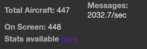
Whereplane.xyz, our little aggregator site for ADSBees, continues to grow! We’re regularly hitting over 2k messages per second with 450+ aircraft now, with sites across the USA and Europe. Not bad, considering that most of these receivers are running on low-gain antennas or sometimes literally on peoples’ kitchen table. We’re at less than 3% of the traffic volume of “real” aggregator sites like airplanes.live, but it’s really fun to see ADSBee installations popping up around the world!