
Happy January! We’re heading into 2026 with a strong start–there’s a lot that’s been happening in ADSBee land. Here’s what we’ve been up to this month.
- Firmware updates
- RF performance improvements
- Surface position decoding
- Oops, more packets
- 200 stars!
- ADSBee in the news
- EAA Airventure Oshkosh 2026
💾 Firmware Updates
This month was a busy one for our firmware monkeys. We published and tested six firmware release candidates, culminating in the latest version 0.9.0-rc11, and made both substantial new features and improvements to RF performance on deployed devices.
📻 RF Performance Improvements
After some dynamic range testing done by an ADSBee user this month, I realized that there were some significant improvements waiting to be made to the preamble detector and demodulator on the ADSBee, particularly regarding high dynamic range performance. Dynamic range is the ratio of the loudest signal you can process to the quietest signal you can process simultaneously. In the case of ADSBee, this is essentially the maximum and minimum range at which you can resolve an aircraft’s transponder signals. While you might assume that a radio receiver capable of receiving
really small
signals would be just fine receiving those same signals if they were
really loud
you would be surprised to learn that (of course) it’s not quite that easy. In the case of the ADSBee, the particular (very performant) log power detector IC that we use to convert received RF power into an analog voltage has some funky non-symmetric behavior with its output voltage. The rise time of the output voltage is quite good (around 40ns), but the fall time can take significantly longer (perhaps 100ns or so). These times sound quite small, but once you consider that we are decoding a 1Mbps manchester coded signal, it becomes apparent that we need to resolve pulses with a minimum pulse width of around 500ns–so small differences in rise or fall time can have a significant impact.
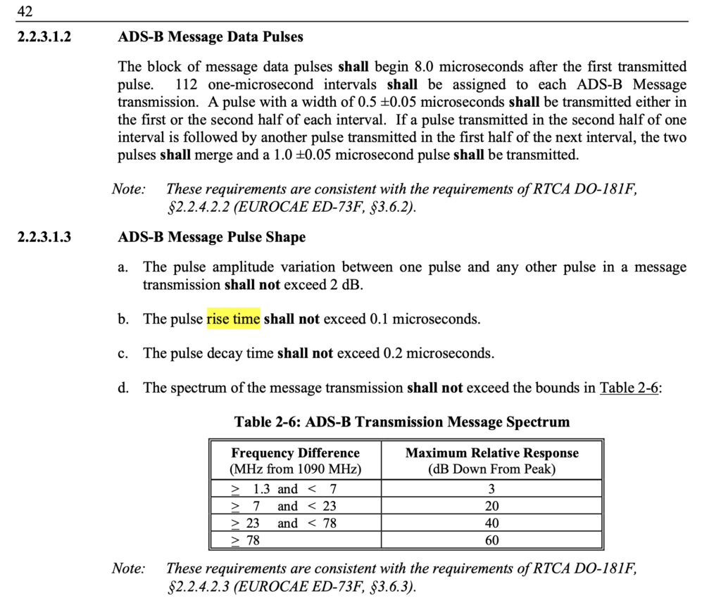
Then, there’s the transponders themselves, which emit RF pulses in compliance with RTCA DO-260C, a standards document that details MOPS (Minimal Operational Performance Specifications) for Mode S transponders. While rise time for signal pulses is capped at 100ns, fall time is allowed to extend to up to 200ns!
If we are resolving a 500ns pulse, which is preceded by a 100ns rise time on the transponder, followed by the 500ns pulse width, then takes 200ns to decay, and then our log power detector takes an additional 100ns to give us a “low” signal on our analog net, we can see the issue; we’re taking almost 900ns to fully resolve the 500ns pulse! At low power levels (for aircraft far away) this isn’t too much of an issue, as the AD8313 isn’t slewing across a significant voltage range, so our rise and fall times are manageable. When aircraft get very close, things get trickier, as high power pulses stretch out the rise (and especially the fall) times on the AD8313, causing adjacent discrete pulses to blend together into one big blob.
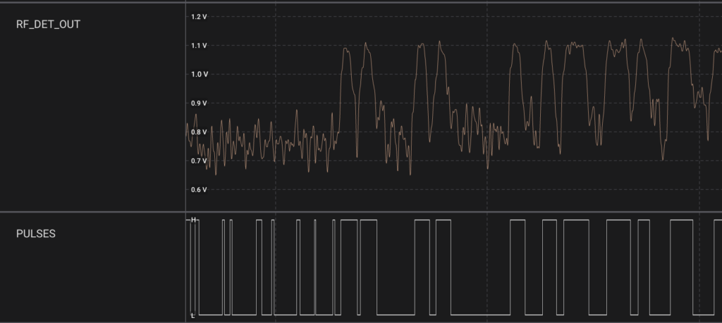
In the image below, we can see the issue at work. This is a capture of a pretty benign packet from a relatively far away aircraft, so it isn’t a “worst case scenario” but does show some of the behaviors in question. The raw RF pulses on RF_DET_OUT have their rise and fall slopes blended together, coming through less as discrete square shaped pulses and more like a craggy mountain range. The PULSES output, which comes from a data slicer circuit with comparator I designed in 2024, shows the output of the analog circuit that converts the analog power waveform that the RP2040 can chew on. In particular, we can see that the blending of the two first pulses creates a very shallow gap between them on the digital waveform, making them pretty hard to differentiate.
These pulses being spaced too close together can make it hard to resolve a preamble lock, and can also lead to bit flips while decoding messages. ADSBee’s PIO program does 5x oversampling for each bit period, allowing me to conduct a “voting” scheme to determine if a given pulse is actually a high or a low.
In the course of optimizing for close-range reception this month, I made a few tweaks to how the preamble detector works.
First, I decreased the number of “low” samples required to classify a pulse as a 0, while increasing the number of “high” samples required to classify the pulse as a 1. The idea behind this was that the AD8313’s rise and fall times are asymmetric, so it’s much easier to get a 1 instead of a 0. This made quite a decent improvement to the successful decode rate of packets being received, suggesting that I was reducing the number of bit errors received when demodulating a message.
Second, I changed the preamble detector to only look for the long period of “0” pulses followed by two “1” pulses in the Mode S preamble, instead of looking for both sets of double pulses. This had the benefit of sidestepping the tricky behavior of the first double pulse in the preamble, which was more likely to blend together into one fat pulse due to some components in the data slicer circuit needing to charge up to the DC bias of the center of the pulse train when packets were first being received. The added benefit of this was that I could re-structure the preamble detector to be much more immune to spurious pulses we would get before the first double pulse in the preamble structure, which were a common cause of missed packets before.
With these two improvements combined, ADSBee users around the world have reported a significant improvements in maximum and minimum effective reception range, as well as number of packets received per second.
If you are using an ADSBee in a close-range context, there are some additional changes you can make to improve sensitivity at high power levels.
- Raise the TL_OFFSET parameter. Increasing TL_OFFSET raises the bias of the comparator that slices the RF_DET_OUT analog waveform into digital pulses. A higher TL_OFFSET value will reduce the sensitivity of the receiver, but will make it more suited to resolving high power packets. For general use and maximum sensitivity, a TL_OFFSET value of 300 to 600 is typical. For high power applications where you don’t care as much about far away air traffic, a TL_OFFSET parameter around 1000 can be used.
- If you are integrating the ADSBee m1090 into a design, forgoing an extra LNA stage to use only the LNA built-in to the m1090 provides about a 20dB reduction in overall gain, allowing reception of higher power signals with fewer issues. This is the recommended configuration for air-to-air receiver applications, where you generally care less about resolving aircraft hundreds of miles away, and more about accurately receiving aircraft that are quite close by.
There are more firmware tweaks I have in mind for further improving dynamic range performance (more on that another time), as well as some potential hardware mods for future revisions. In the meantime, I highly encourage you to update your ADSBee 1090U to the newest release candidate of 0.9.0 to try out the improved performance for yourself!
🚗 Surface Position Decoding
One of the most persistent requests from ADSBee users who are testing the ADSBee 1090U in general aviation applications has been to add local surface position decoding. Right now, when ADSBee users connect to an iPad or a drone flight controller, all aircraft locations reported by the ADSBee are decoded on-board using some rather extensive embedded processing and filtering of the received packets. Up until this month, only packets for aircraft in the air were processed for Mode S, while both airborne and on-ground packets were processed for UAT. This was due to Mode S’s rather convoluted surface position encoding algorithm, which uses Compact Position Reporting on an even smaller grid size than Mode S airborne position messages, requiring an entirely separate decoder algorithm as well as a reference location nearby on earth. Since sensing aircraft on the ground is a relatively niche application, this task got punted for quite a few months, until I finally got around to it in the last few weeks!
In the course of implementing this feature, I had to sort out how to seed the ADSBee with a reference position in order to allow it to decode locations of surface targets like airport vehicles and airplanes. This location could afford to be relatively coarse, but still needed to be within around 45 nautical miles of the surface target. To that end, I’ve added a new AT command called AT+RX_POSITION that allows a receiver position to be set to a fixed receiver location, bootstrapped by stealing the location from the lowest altitude aircraft in the aircraft dictionary (generally a good proxy for how close the aircraft is to the receiver, since low altitude aircraft transmit at lower power and are more easily occluded by terrain), or bootstrapped by stealing the location from an aircraft with a given ICAO address (useful if you are using the ADSBee from onboard a plane). In the future, when GNSS receiver support is added, the ADSBee will be able to seed its receiver location from an external GNSS module as well.
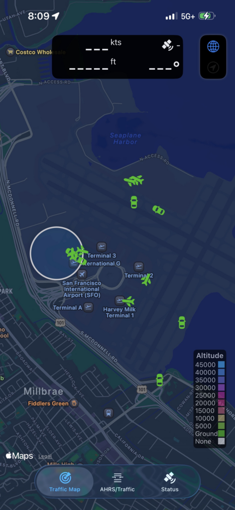
Since the release of firmware version 0.9.0-rc11, ADSBees now report aircraft surface positions! If you connect ADSBee to an app on your phone like AeroADSB, you should see the positions of nearby taxiing aircraft and surface vehicles. Here’s a quick screenshot of some aircraft and vehicles I saw out the window of a plane I was on at KSFO recently.
📈 Oops, more packets
Another significant firmware improvement this month was made by one of our community members, @justin4046. Justin noticed that our function for validating squitter frames was only validating Downlink Format (DF)=11 (spontaneous acquisition squitter packets), and was discarding all squitter packets with DF=0,4,5,16,20,21. These particular packet formats are a bit tricky, since the aircraft’s ICAO address is overlaid with the CRC of the packet via XOR, so the only way you can validate the packet checksum is to thumb through every ICAO address in your aircraft dictionary to see if one of them matches the calculated checksum of the packet. The firmware infrastructure for ADSBee was built with this operation in mind, but the dictionary validation feature was broken and had gone previously unnoticed–until now! Thanks to Justin’s PR, ADSBee now properly forwards many additional squitter packet formats for validation by the aircraft dictionary.
These additional squitter data frames don’t provide much actionable information for onboard decoding, since they don’t include full aircraft position information like extended squitter ADS-B packets, but they do provide some information like altitude and callsign (DF=4,5), and may be of use for users forwarding data to external decoders like readsb, which have access to more information and compute.
The result of this squitter packet validation improvement, combined with the aformentioned RF performance improvements, is that ADSBees are receiving a lot of packets! On user has reported receive rates of nearly 500 msgs/sec on a single receiver (Mode S only).
When all of this data gets shoved together with UAT downlink and uplink packets, then sent to 5+ aggregators simultaneously via WiFi, we’ve started to see some throughput limitations that cause the ADSBee’s ESP32 to reboot occasionally while under heavy packet load in the WiFi STA configuration (uploading data to the internet or local docker containers). This is certainly not the worst problem to have (we are receiving too much data), but it’s on the hot list for fixes this next month. Stay tuned!
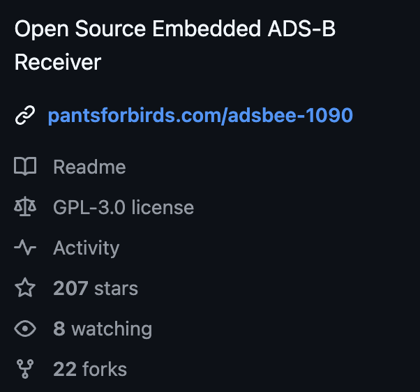
⭐ 200 Stars!
Wow! The ADSBee GitHub repository has crossed the 200 star mark. Thank you to everyone who has tried out a receiver, or just stopped by to have a peek. We’re building a cool thing together!
📰 ADSBee in the News
ADSBee was featured in a Hackaday article. If you’ve joined the project after reading about us there, welcome! We’re so excited to have you along. It’s always a great honor to see any of my projects on a website frequented by so many nteresting and enthusiastic people.
We also got featured on the RTL-SDR blog and linked on Adafruit!
🛬 EAA Airventure Oshkosh 2026
Pants for Birds will have a vendor booth at EAA Airventure Oshkosh in 2026! That’s about all there is to know about it for now. More to come 👀