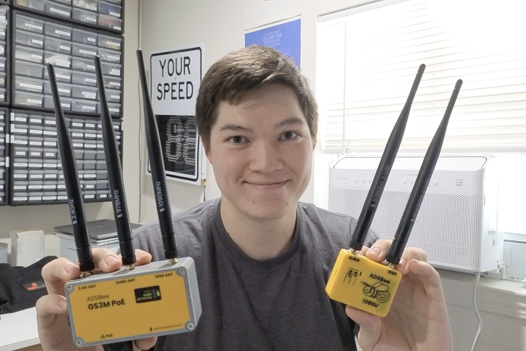
Howdy bee friends! It’s been a very busy month at Pants for Birds. Here’s what we’ve been up to!
💾 Firmware
📶 0.9.0-rc15
We have a new firmware release candidate available for testing, 0.9.0-rc15! This release candidates includes a number of significant features and bug fixes that were introduced within the past month of development by Pants for Birds and members of the ADSBee developer community. Here’s a few of the big ones:
Fixes FIS-B weather messages forwarded over GDL90 / WiFi UDP. This means UAT weather information now streams properly to apps like Foreflight / Avare / FlyQ EFB!
Introduces a new CSBee protocol version 3, mostly compatible with CSBee protocol version 2 (more info below).
Properly distinguishes between direct aircraft contacts and rebroadcasts on both Mode S and UAT. Mode S aircraft have a new “non transponder” bit flag to indicate they are being rebroadcast, and UAT aircraft include a 4-bit address qualifier at the beginning of their ICAO address (which can be up to 28 bits instead of 24 bits). These details are available as part of CSBee protocol version 3, and the expanded ICAO address for UAT aircraft means they are now assigned separate entries in the aircraft dictionary.
MAVLINK component ID (thanks @AndersonRayner) and protocol versions corrected in MAVLINK1/MAVLINK2 reporting protocols.
General GDL90 improvements (thanks @snax01).
Screenshot from @snax01 showing ADSBee’s decoded UAT uplink packets forwarded to FlyQ EFB.
⛅ 0.9.0 Stable is on the horizon!
We’re in the final stretch before we cut a stable 0.9.0 firmware. The 0.9.0 release candidate train started in September of last year with the initial implementation of dual band receiver firmware on ADSBee 1090U, and we’ve spent a significant amount of time massively improving performance, enhancing stability, and adding key features since then. There’s been a list of important bugs to fix throughout the duration of our run of 0.9.0 release candidate firmwares, and I’m happy to say that we’ve systematically worked through just about all of them at this point. Since September of last year, we’ve gone from what was essentially a dual band proof of concept ADS-B receiver to a reliable receiver workhorse that’s been deployed in hundreds of locations across the world on drones, balloons, ground stations, tactical radios, ground vehicles, and experimental avionics systems.
Work will not be slowing down once we reach a 0.9.0 firmware milestone that meets our criteria for a “stable” release. I’m excited to share more about some of the very interesting plans we have in the pipe!
🔧 Hardware
🛒 ADSBee 1090U Stock
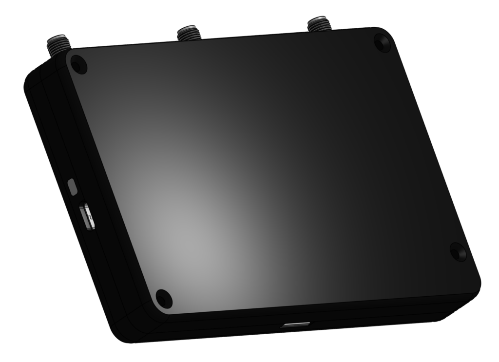
Our most recent round of ADSBee 1090U’s is just about sold out! If you need a receiver soon, there’s still a few in stock. We have another build in process and should have additional stock landing before the end of this month.
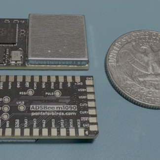
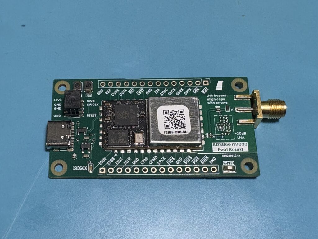
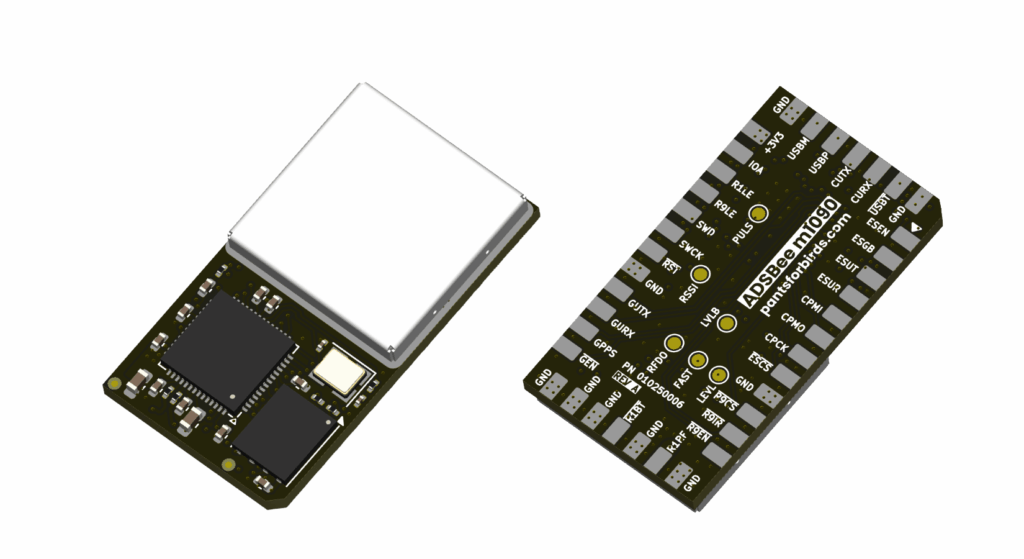
Our first production run of ADSBee m1090’s has arrived. If you are looking to build ADSBee 1090U style dual band ADS-B reception into your custom design, these modules are a fantastic way to do it. We have bulk pricing available up to 100 unit quantities!
We are pleased to introduce our EU distributor, Hentronic! If you are looking for ADSBee in Europe or the UK, and want to avoid expensive international shipping from our US shop, Hentronic is an excellent option. Shipping to most EU locations is very affordable, and no import tariff is required.
📅 Events
❎ XPonential
I’ll be at XPonential as an attendee (not an exhibitor) next week. If you have an interest in open source ADSB for your embedded application, and you’ll be at the show, I’d love to meet up and have a chat!
🤖 Open Sauce
We are happy to announce that ADSBee has been accepted to exhibit at Open Sauce this year! Catch us showing off some new projects (and products) before we do a crazy all night transportation bender to get to EAA Airventure which starts the following Monday (hoo boy).
🛩️ EAA Airventure
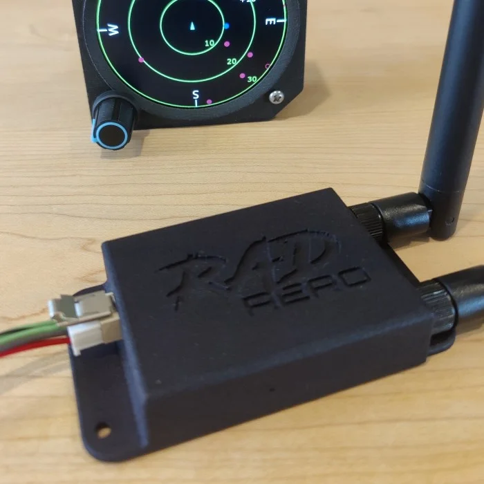
ADSBee will be exhibiting at EAA Airventure, along with one of our partner businesses, RAD Aero! RAD Aero builds Electronic Flight Information Systems (EFIS) for experimental aircraft, along with a CAN bus ADS-B receiver based on the ADSBee m1090 module.
Bryan at RAD Aero (@snax01 on Github) has been a very helpful open source contributor and beta tester for the ADSBee 1090 firmware, and we’re excited to be attending the World’s Coolest Airshow with him.
👀 New Project
We’ve been busy cooking up a major new project based on the ADSBee m1090 module. Things are still in the early prototype phase, but we have a device name and preliminary feature list that’s ready to share very soon. Stay tuned for a separate announcement!
In the meantime, here’s what the less interesting side of it looks like 🙂
ADSBee m1090’s have also been on backorder for a few weeks. Fortunately, our initial volume production run is currently in progress, and we expect to receive stock and fulfill backorders within the next few weeks! In the meantime, ADSBee m1090 Eval Boards are still available, in case you’d like to try out an m1090 module in your project.
🇪🇺 EU distribution coming soon
I’ll wait until we have all of our ducks in a row before making the official announcement, but Pants for Birds LLC is in the final stages of bringing on an official distributor for ADSBee products based in Germany! If you’re looking to get an ADSBee, or parts for an ADSBee, in the EU or nearby regions, this will be a very convenient option in the near future. Stay tuned!
🧮 Something different
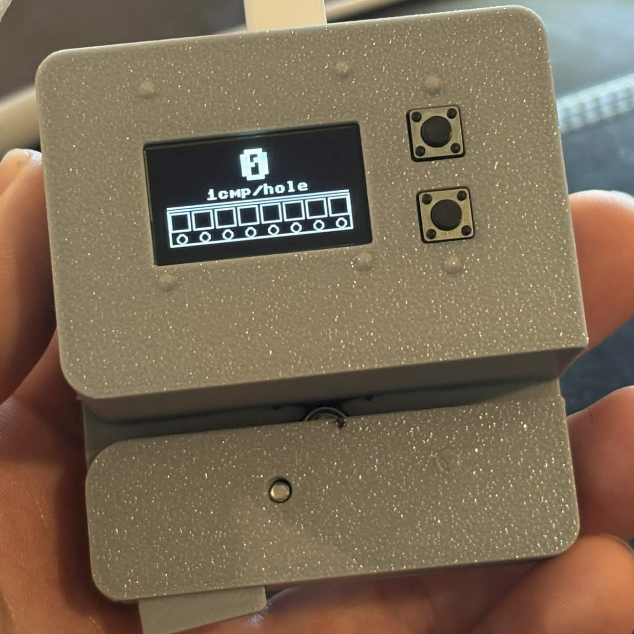
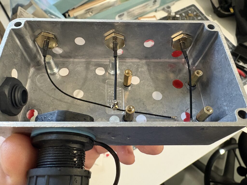
In the course of consigning many thousands of parts for ADSBee builds this month, I made a spur of the moment decision to build a new tool for counting SMT components! I call it Dotterboard, because it counts dots (the 4mm pitch holes in SMT tape). It fixes a few gripes I had with existing solutions, in that it works with all widths / pocket depths / transparencies / thicknesses of SMT tape, and can be adjusted to work with various component pitches as well.
I’ve created a #dotterboard channel on our Discord server in case people are interested in discussing the design or building their own, and I’m toying with the idea of spinning a PCB for the front panel and MCU, to save people the trouble of wire wrapping or soldering their own device. If you want to build (or buy) one of these, I’d love to hear about it!
👀 New designs coming soon…
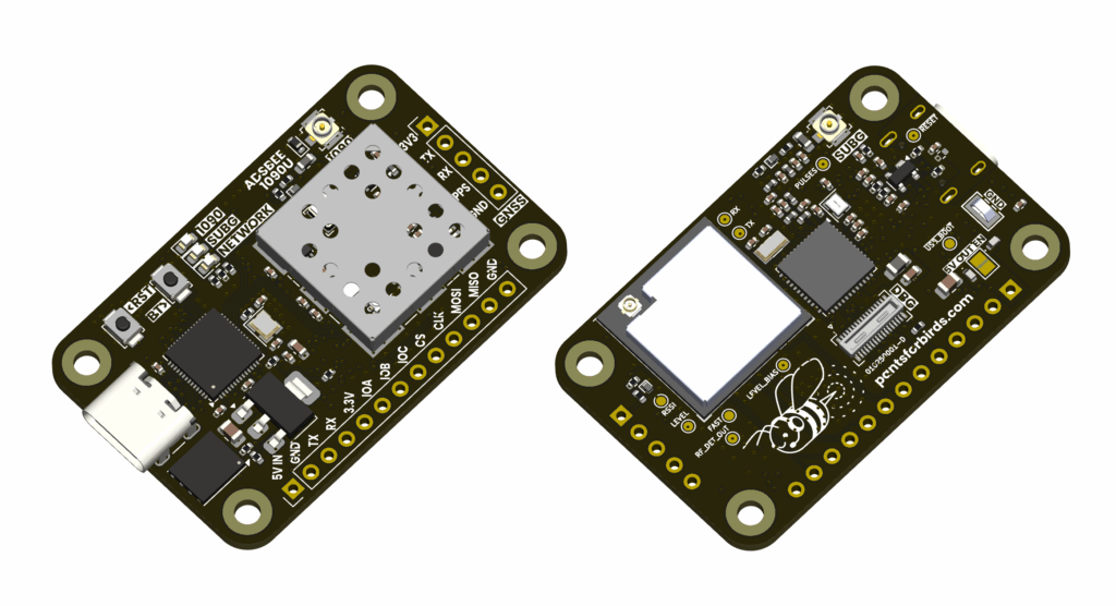
Pants for Birds has some new designs in the pipeline that will complement the ADSBee 1090U in two different areas of operation. One product will focus exclusively on extreme low power and minimal size solutions for UAS and lightweight aerial vehicles, while the other will be tailored towards general aviation applications.
These new designs will draw heavily upon the existing codebase built for the ADSBee 1090U, and will be a driving force for adding many frequently requested features to the unified ADSBee 1090 firmware (such as GPS receiver integration and a proper web GUI for the ADSBee). Two talented individuals have joined the Pants for Birds development team to bring these products to life, and I’m excited to introduce them to the community someday soon. In the meantime, we have a lot of code to write (and boards to build)!
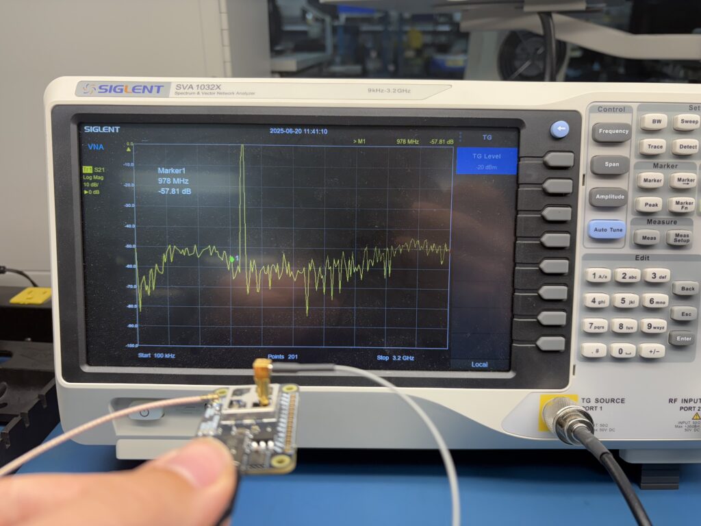
Disclaimer: Don’t do this unless you know what you’re doing, and absolutely don’t stick an antenna onto the test signal source I’m about to describe. Test signal sources are intended for low power use in a controlled environment only, so that they don’t interfere with legitimate transmissions and land you in legal trouble.
When building an ADS-B receiver, it can be helpful to have a low power Mode S signal source available to test with. There are many accounts of building Mode S test signal sources out of transmit-capable software defined radios (SDRs) like the HackRF. These fit the bill for a variety of use cases, ranging from legitimate purposes like Mode S receiver R&D to drawing JD Vance over Mar-a-lago.
SDRs are capable of a lot more than basic Mode S modulation, but this additional capability comes with quite a bit of overhead. Instead of the simple on/off pulse keying pattern used by Mode S, SDRs read from a buffer of I/Q samples, which represent the magnitudes of in-phase (I) and quadrature (Q) RF signals that are mixed to form an output signal. By varying the amplitude of these two signals (think a sine wave for I, and a sine wave phase shifted by 90 degrees for Q) and combining them, the SDR can generate just about any arbitrary RF waveform, limited only by the rate at which it can consume new samples and physical limitations of its hardware. With a high enough sample rate, and capable frontend hardware, SDRs can mimic extremely advanced waveforms like WiFi and LTE, which transmit across a wide frequency range (bandwidth) simultaneously.
The extra capability of transmit-capable SDRs comes with a cost. Usually, they need a companion computer like a laptop or Raspberry Pi to feed them with samples, and if you’re storing a few seconds or minutes of messages with a high sample rate, the size of the I/Q files being stored then streamed to the SDRs can get quite big (Gigabytes). Of course, there’s also the monetary cost of the SDR itself! The HackRF runs about $340, and prices generally go up from there.
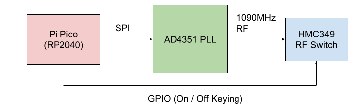
In the spirit of the ADSBee, which uses a Pi Pico’s PIO peripheral to receive Mode S messages, I figured that it wouldn’t be that hard to make a device that transmits Mode S messages using RP2040 PIO and some basic RF hardware. As a plus, I would have a great deal of control over the actual waveforms I was transmitting, since the RP2040 can have its PIO run at up to 200MHz (if you up the system clock rate to 200MHz), and could build a very simple low-bandwidth interface for transmitting packets, where instead of sending a big blob of IQ samples to the test transmitter I could simply send the contents of the packet I wanted to transmit.
Mode S uses on-off keying, so the only necessary parts are some kind of RF signal source that could generate out 1090MHz signal, and a way of modulating that signal on and off very quickly (to form the 1MHz Manchester coded pulse stream used to encode the message).
RF signal sources can be found pretty readily in the form of VCOs (Voltage Controlled Oscillators) which can be integrated into PLLs (Phase Locked Loops) that multiply a reference signal from a crystal oscillator (e.g. 25MHz) into a higher frequency RF signal (e.g. the 1090MHz carrier used for Mode S). After some hunting on Amazon, I found an inexpensive PLL dev board for $23 using an ADF4351 PLL that I managed to get working well for synthesizing my 1090MHz signal. The AD4351 receives configuration commands over SPI, which was easy to set up via the Pi Pico. It did take some tuning of various parameters to get the PLL stable, but it seems to work pretty well for the most part, and a digital lock signal can be used to restart the PLL whenever it loses lock.
Keying RF signal sources on and off can be done, in its simplest form, by an RF switch. Some more Amazon scrounging yielded an HMC349 RF switch def board for just $14, which I hooked up to a digital output from the RP240 PIO peripheral to enable my on-off keying for sending messages.
The dirt simple block diagram of a minimal Mode S Transponder looks something like this:
So, there you have it! A Mode S test signal source for less than $40. Note that calling this a full “Mode S Transponder” is a bit clickbait-ey, since a fully featured transponder needs to be able to receive BPSK (binary phase shift-keyed) secondary surveillance uplink messages on 1030MHz, which is quite a bit more complicated. Maybe we will come back to that another time! For the time being, this simple signal source has been more than enough to provide a number of valuable insights while testing ADSBee.
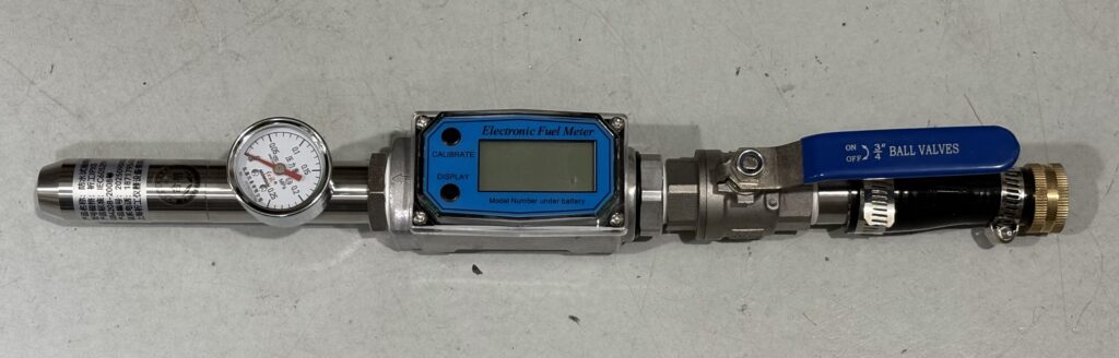
I extended the functionality of the basic Mode S test signal device by adding a series of switchable PE4302 attenuators to the output, allowing me to set a variable 93dB of attenuation on the transponder output. This was critical for testing ADSBee’s dynamic range (more on that later), with the ability to generate a series of transponder messages at a wide range or power levels, to simulate aircraft both close by and far away.
Here’s what the actual build looks like! I 3D printed a big base plate to stick everything to, and used a cursed combination of wire wrap, crimped ferrules, and Dupont pin headers to wire everything together. Note that the RF switch is SPDT; when the switch is “closed”, the RF signal flows into the series of 3 step attenuators. When the switch is “open”, the RF signal flows to a 50 Ohm terminator to minimize reflections.
Even though the RF signal power coming from this test fixture is pretty low (+5dBm), and I never connect it to any antennas, the radiated emissions from the open PCB transmission lines and possibly suspect RF terminations is enough to trigger some of my more sensitive ADSB receivers when they are nearby. This rig definitely needs some shielding (and/or or less exposed PCB layout) for use in an unshielded environment.
If you’re curious about the BOM for this build, I’ve included some links below. Firmware and schematics aren’t provided, because, well, if you know what you’re doing with this you probably can figure those out pretty quickly yourself (and I don’t want to be in the business of distributing schematics for non-certified Mode S transponders that people could use to get in trouble).
Pi Pico: 1x $5
ADF4351 PLL: 1x $23/ea (Note: this isn’t the exact one I used, since that one is no longer stocked. Beware the ADF4350 PLL’s, I wasn’t able to get one of those to work for some reason, they may have a busted layout).
At the time of this writing, both the ADSBee 1090U and ADSBee m1090 are sold out and on backorder. We expect another batch of ADSBee 1090U’s to land around the end of this month, and a batch of ADSBee m1090’s to land sometime early to mid April.
Backorders are first come first serve, so it doesn’t hurt to place an order in the meantime!
Firmware version 0.9.0-RC13 fixes some bugs discovered and corrected by community members related to UAT downlink messages being forwarded without proper Forward Error Correction applied. Packets were being corrected on-device, but then forwarded in their uncorrected form, leading to some aircraft showing up with garbled callsigns or incorrect altitude as they got further from the receiver! Thank you to @justin4046 for his work on this issue.
This update also fixes some Mode S Beast feeds where ADSBee wasn’t sending its unique base station ID (UUID) at the start of the feed, causing online exchanges like airplanes.live to assign receivers a randomly generated UUID. This bug was only present in some Mode S Beast feed modes–if you notice that your map is missing from an aggregator after updating your firmware, double check your UUID to see whether it’s been changed to the UUID stored for that particular feed on your device! Thank you to @justin4046 for submitting a fix to this issue.
Signal strength and signal quality were added to each aircraft report over CSBee; these values were being received before, but weren’t yet stored in the aircraft dictionary or correctly printed in CSBee messages.
For developers’ convenience, a build script was added to the repo to build firmware images for all three processors. Thanks @pitchlinkaero!
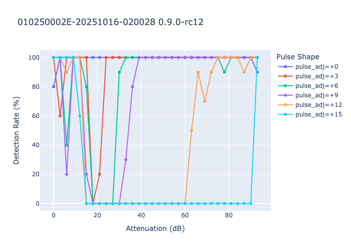
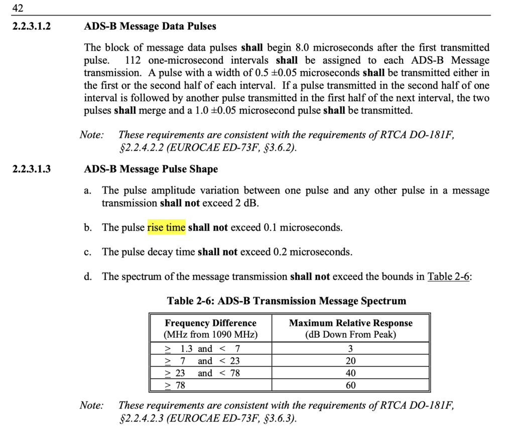
Last but certainly not least, RC13 includes a full re-write of the PIO preamble detector and demodulator code to further improve dynamic range across a variety of pulse shapes permitted by the DO-260C standard (Mode S transponder minimum operational performance specifications). While most aircraft use pulses with just a few ns of rise / fall time, the actual transponder spec does permit rise times as slow as 100ns and fall times as slow as 200ns.
The previous implementation of the ADSBee preamble detector had a pretty hard time with wider pulse shapes, since they interacted with the non-symmetric rise / fall behavior of the AD8313 power detector in the ADSBee’s RF frontend. I added custom pulse shape adjustments to the PIO code in the Mode S test fixture, and was able to perform sweeps at a variety of power levels and pulse shapes to see how the ADSBee fared, using proportion of packets received as a performance metric.
The plot below shows performance with RC12 firmware. Each +1 of the pulse_adj parameter corresponds to a widening of each pulse by 16ns, and the attenuation parameter refers to the amount of attenuation applied to the +5dBm RF signal coming from the test fixture’s signal generator. We can see that wide pulse shapes (240ns additional pulse width) drop out even for low powered signals around -85dBm, while narrower pulse shapes fare better until around -15dBm or so.
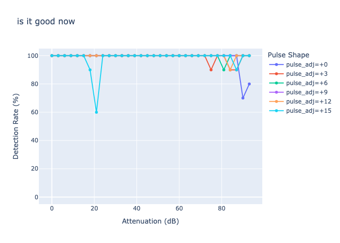
After some significant re-writing of the preamble detector and demodulator (including some clever hacks), performance was significantly improved, with excellent performance across 90dB of dynamic range for most pulse shapes.
The particular changes used to achieve this include changing the demodulator from a dynamic clock recovery algorithm to a fixed sampling routine (made possible since the cumulative pulse position error is relatively tight according to the DO-260C spec).
Another hack was the introduction of a unique “clock stretching” algorithm that delays sample timing based on the RSSI of the preamble (the AD8313 has a much slower fall than rise time, meaning it’s best to sample later in the bit period for high power messages, since the slow fall time causes troughs between pulses to lag in phase and narrow as receive power increases). This clock stretching is achieved by sampling at a fixed interval after each expected positive pulse in the preamble. If the sample reads high, we can assume that the signal power is high enough that we’re still in the extended fall time of the pulse coming from the AD8313. This stretch is repeated for each pulse in the preamble (4 total), providing four “steps” of phase lag that can be applied to the subsequent sampling timing dependent on the power of the incoming transmission. This may reduce the accuracy of MLAT timing, since higher power messages get their sampling start time delayed by some number of nanoseconds compared to low power messages, but we could calibrate this out after the fact by changing MLAT timer values based on recorded message RSSI if it does indeed become a problem.
I’m excited to hear about results from the field with these dynamic range improvements! The optimizations to the PIO programming were carefully balanced to improve dynamic range on the test fixture while also keeping receive performance on an actual antenna (with real planes in the air around the receiver) relatively equivalent to the past firmware.
Firmware version RC14 fixes an ADC configuration bug that was introduced in RC13, which was causing RP2040 MCU temperature values to read too high, and also fixes a bug in the Mode S decoder that caused some aircraft to report incorrect altitudes when they sent a particular format of Airborne Position message that utilized Gillham-coded altitude values, as well as some other miscellaneous bug fixes. If you are using an ADSBee with local position decoding (e.g. displaying air traffic via MAVLINK / CSBee / GDL90), I highly recommend applying this update!
🌎 Whereplane.xyz
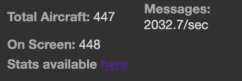
Whereplane.xyz, our little aggregator site for ADSBees, continues to grow! We’re regularly hitting over 2k messages per second with 450+ aircraft now, with sites across the USA and Europe. Not bad, considering that most of these receivers are running on low-gain antennas or sometimes literally on peoples’ kitchen table. We’re at less than 3% of the traffic volume of “real” aggregator sites like airplanes.live, but it’s really fun to see ADSBee installations popping up around the world!
Happy January! We’re heading into 2026 with a strong start–there’s a lot that’s been happening in ADSBee land. Here’s what we’ve been up to this month.
Firmware updates
RF performance improvements
Surface position decoding
Oops, more packets
200 stars!
ADSBee in the news
EAA Airventure Oshkosh 2026
💾 Firmware Updates
This month was a busy one for our firmware monkeys. We published and tested six firmware release candidates, culminating in the latest version 0.9.0-rc11, and made both substantial new features and improvements to RF performance on deployed devices.
📻 RF Performance Improvements
After some dynamic range testing done by an ADSBee user this month, I realized that there were some significant improvements waiting to be made to the preamble detector and demodulator on the ADSBee, particularly regarding high dynamic range performance. Dynamic range is the ratio of the loudest signal you can process to the quietest signal you can process simultaneously. In the case of ADSBee, this is essentially the maximum and minimum range at which you can resolve an aircraft’s transponder signals. While you might assume that a radio receiver capable of receiving
really small
signals would be just fine receiving those same signals if they were
really loud
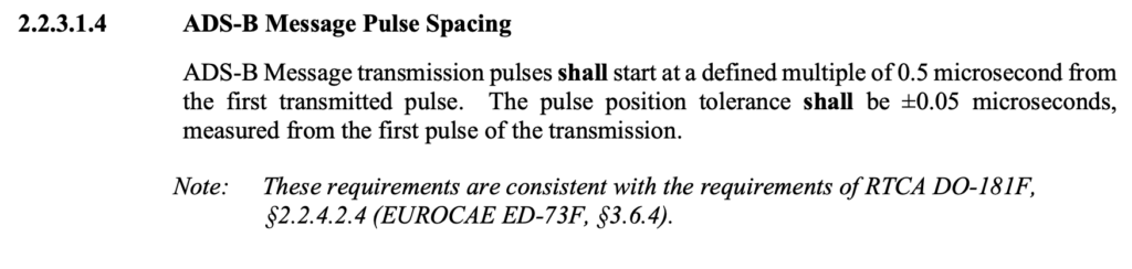
you would be surprised to learn that (of course) it’s not quite that easy. In the case of the ADSBee, the particular (very performant) log power detector IC that we use to convert received RF power into an analog voltage has some funky non-symmetric behavior with its output voltage. The rise time of the output voltage is quite good (around 40ns), but the fall time can take significantly longer (perhaps 100ns or so). These times sound quite small, but once you consider that we are decoding a 1Mbps manchester coded signal, it becomes apparent that we need to resolve pulses with a minimum pulse width of around 500ns–so small differences in rise or fall time can have a significant impact.
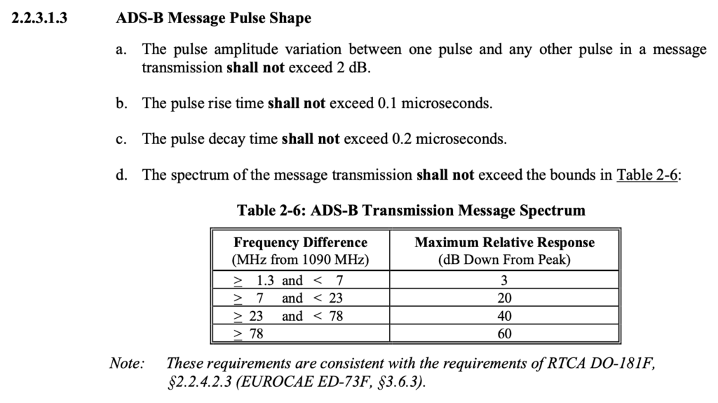
An excerpt from DO-260C detailing pulse shape requirements for Mode S transponders.
Then, there’s the transponders themselves, which emit RF pulses in compliance with RTCA DO-260C, a standards document that details MOPS (Minimal Operational Performance Specifications) for Mode S transponders. While rise time for signal pulses is capped at 100ns, fall time is allowed to extend to up to 200ns!
If we are resolving a 500ns pulse, which is preceded by a 100ns rise time on the transponder, followed by the 500ns pulse width, then takes 200ns to decay, and then our log power detector takes an additional 100ns to give us a “low” signal on our analog net, we can see the issue; we’re taking almost 900ns to fully resolve the 500ns pulse! At low power levels (for aircraft far away) this isn’t too much of an issue, as the AD8313 isn’t slewing across a significant voltage range, so our rise and fall times are manageable. When aircraft get very close, things get trickier, as high power pulses stretch out the rise (and especially the fall) times on the AD8313, causing adjacent discrete pulses to blend together into one big blob.
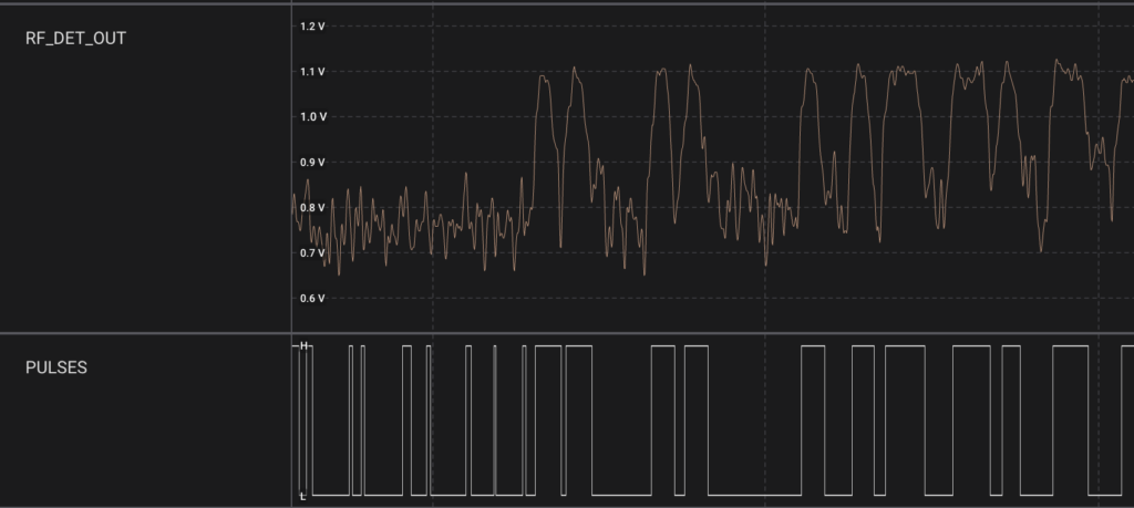
In the image below, we can see the issue at work. This is a capture of a pretty benign packet from a relatively far away aircraft, so it isn’t a “worst case scenario” but does show some of the behaviors in question. The raw RF pulses on RF_DET_OUT have their rise and fall slopes blended together, coming through less as discrete square shaped pulses and more like a craggy mountain range. The PULSES output, which comes from a data slicer circuit with comparator I designed in 2024, shows the output of the analog circuit that converts the analog power waveform that the RP2040 can chew on. In particular, we can see that the blending of the two first pulses creates a very shallow gap between them on the digital waveform, making them pretty hard to differentiate.
These pulses being spaced too close together can make it hard to resolve a preamble lock, and can also lead to bit flips while decoding messages. ADSBee’s PIO program does 5x oversampling for each bit period, allowing me to conduct a “voting” scheme to determine if a given pulse is actually a high or a low.
In the course of optimizing for close-range reception this month, I made a few tweaks to how the preamble detector works.
First, I decreased the number of “low” samples required to classify a pulse as a 0, while increasing the number of “high” samples required to classify the pulse as a 1. The idea behind this was that the AD8313’s rise and fall times are asymmetric, so it’s much easier to get a 1 instead of a 0. This made quite a decent improvement to the successful decode rate of packets being received, suggesting that I was reducing the number of bit errors received when demodulating a message.
Second, I changed the preamble detector to only look for the long period of “0” pulses followed by two “1” pulses in the Mode S preamble, instead of looking for both sets of double pulses. This had the benefit of sidestepping the tricky behavior of the first double pulse in the preamble, which was more likely to blend together into one fat pulse due to some components in the data slicer circuit needing to charge up to the DC bias of the center of the pulse train when packets were first being received. The added benefit of this was that I could re-structure the preamble detector to be much more immune to spurious pulses we would get before the first double pulse in the preamble structure, which were a common cause of missed packets before.
With these two improvements combined, ADSBee users around the world have reported a significant improvements in maximum and minimum effective reception range, as well as number of packets received per second.
If you are using an ADSBee in a close-range context, there are some additional changes you can make to improve sensitivity at high power levels.
Raise the TL_OFFSET parameter. Increasing TL_OFFSET raises the bias of the comparator that slices the RF_DET_OUT analog waveform into digital pulses. A higher TL_OFFSET value will reduce the sensitivity of the receiver, but will make it more suited to resolving high power packets. For general use and maximum sensitivity, a TL_OFFSET value of 300 to 600 is typical. For high power applications where you don’t care as much about far away air traffic, a TL_OFFSET parameter around 1000 can be used.
If you are integrating the ADSBee m1090 into a design, forgoing an extra LNA stage to use only the LNA built-in to the m1090 provides about a 20dB reduction in overall gain, allowing reception of higher power signals with fewer issues. This is the recommended configuration for air-to-air receiver applications, where you generally care less about resolving aircraft hundreds of miles away, and more about accurately receiving aircraft that are quite close by.
There are more firmware tweaks I have in mind for further improving dynamic range performance (more on that another time), as well as some potential hardware mods for future revisions. In the meantime, I highly encourage you to update your ADSBee 1090U to the newest release candidate of 0.9.0 to try out the improved performance for yourself!
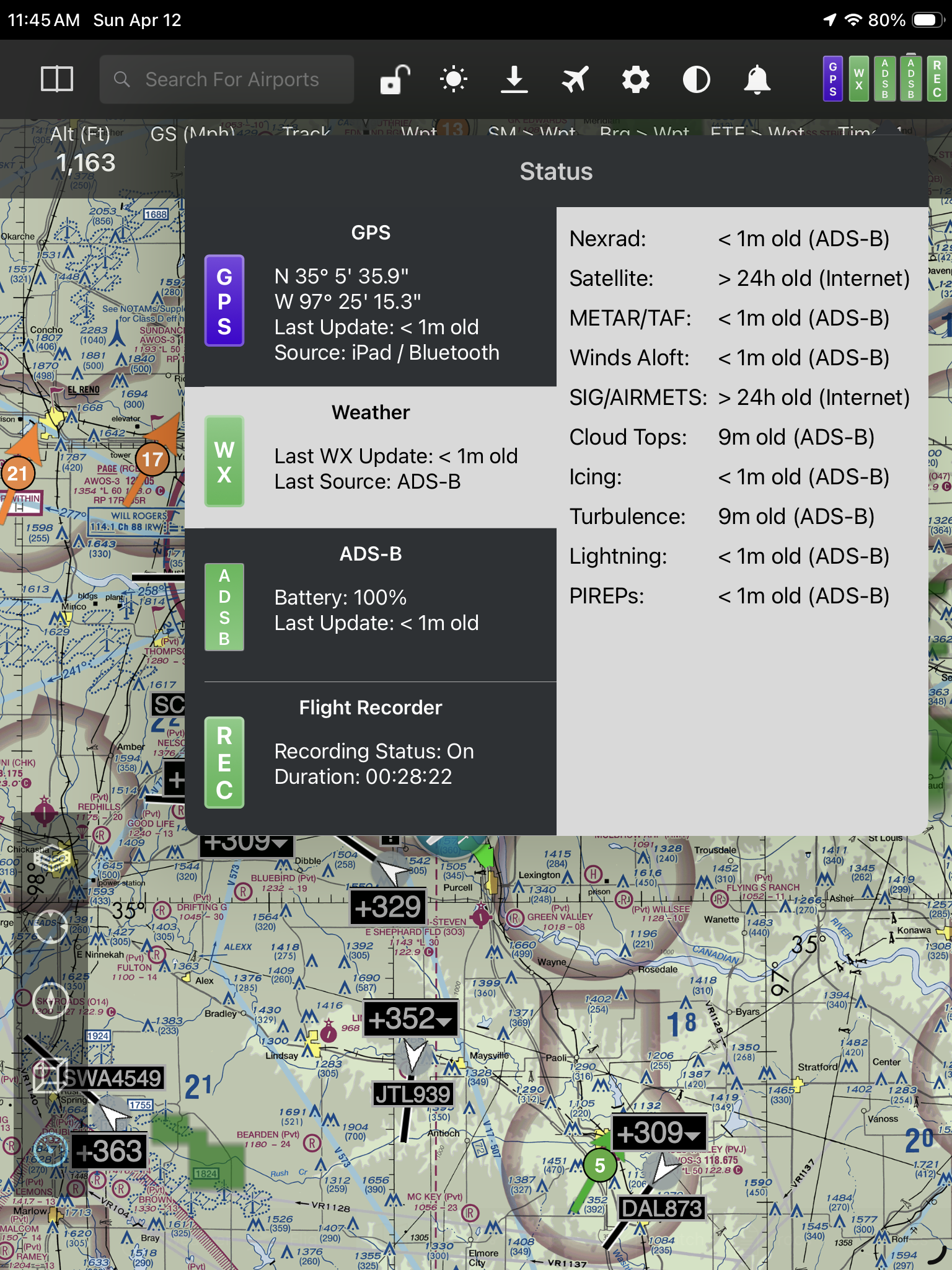
🚗 Surface Position Decoding
One of the most persistent requests from ADSBee users who are testing the ADSBee 1090U in general aviation applications has been to add local surface position decoding. Right now, when ADSBee users connect to an iPad or a drone flight controller, all aircraft locations reported by the ADSBee are decoded on-board using some rather extensive embedded processing and filtering of the received packets. Up until this month, only packets for aircraft in the air were processed for Mode S, while both airborne and on-ground packets were processed for UAT. This was due to Mode S’s rather convoluted surface position encoding algorithm, which uses Compact Position Reporting on an even smaller grid size than Mode S airborne position messages, requiring an entirely separate decoder algorithm as well as a reference location nearby on earth. Since sensing aircraft on the ground is a relatively niche application, this task got punted for quite a few months, until I finally got around to it in the last few weeks!
In the course of implementing this feature, I had to sort out how to seed the ADSBee with a reference position in order to allow it to decode locations of surface targets like airport vehicles and airplanes. This location could afford to be relatively coarse, but still needed to be within around 45 nautical miles of the surface target. To that end, I’ve added a new AT command called AT+RX_POSITION that allows a receiver position to be set to a fixed receiver location, bootstrapped by stealing the location from the lowest altitude aircraft in the aircraft dictionary (generally a good proxy for how close the aircraft is to the receiver, since low altitude aircraft transmit at lower power and are more easily occluded by terrain), or bootstrapped by stealing the location from an aircraft with a given ICAO address (useful if you are using the ADSBee from onboard a plane). In the future, when GNSS receiver support is added, the ADSBee will be able to seed its receiver location from an external GNSS module as well.
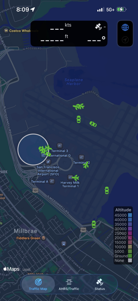
Since the release of firmware version 0.9.0-rc11, ADSBees now report aircraft surface positions! If you connect ADSBee to an app on your phone like AeroADSB, you should see the positions of nearby taxiing aircraft and surface vehicles. Here’s a quick screenshot of some aircraft and vehicles I saw out the window of a plane I was on at KSFO recently.
📈 Oops, more packets
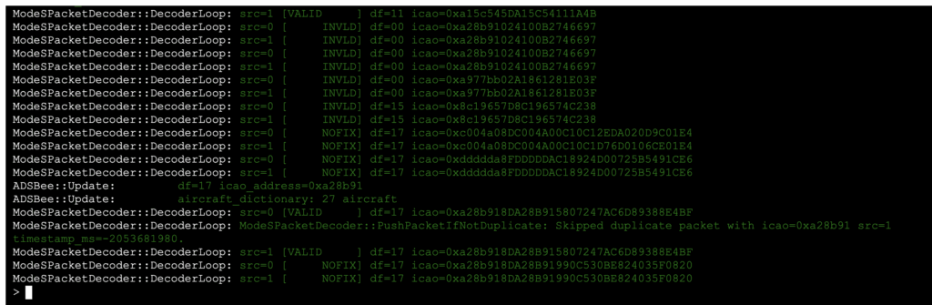
Another significant firmware improvement this month was made by one of our community members, @justin4046. Justin noticed that our function for validating squitter frames was only validating Downlink Format (DF)=11 (spontaneous acquisition squitter packets), and was discarding all squitter packets with DF=0,4,5,16,20,21. These particular packet formats are a bit tricky, since the aircraft’s ICAO address is overlaid with the CRC of the packet via XOR, so the only way you can validate the packet checksum is to thumb through every ICAO address in your aircraft dictionary to see if one of them matches the calculated checksum of the packet. The firmware infrastructure for ADSBee was built with this operation in mind, but the dictionary validation feature was broken and had gone previously unnoticed–until now! Thanks to Justin’s PR, ADSBee now properly forwards many additional squitter packet formats for validation by the aircraft dictionary.
These additional squitter data frames don’t provide much actionable information for onboard decoding, since they don’t include full aircraft position information like extended squitter ADS-B packets, but they do provide some information like altitude and callsign (DF=4,5), and may be of use for users forwarding data to external decoders like readsb, which have access to more information and compute.
The result of this squitter packet validation improvement, combined with the aformentioned RF performance improvements, is that ADSBees are receiving a lot of packets! On user has reported receive rates of nearly 500 msgs/sec on a single receiver (Mode S only).
When all of this data gets shoved together with UAT downlink and uplink packets, then sent to 5+ aggregators simultaneously via WiFi, we’ve started to see some throughput limitations that cause the ADSBee’s ESP32 to reboot occasionally while under heavy packet load in the WiFi STA configuration (uploading data to the internet or local docker containers). This is certainly not the worst problem to have (we are receiving too much data), but it’s on the hot list for fixes this next month. Stay tuned!
⭐ 200 Stars!
Wow! The ADSBee GitHub repository has crossed the 200 star mark. Thank you to everyone who has tried out a receiver, or just stopped by to have a peek. We’re building a cool thing together!
📰 ADSBee in the News
ADSBee was featured in a Hackaday article. If you’ve joined the project after reading about us there, welcome! We’re so excited to have you along. It’s always a great honor to see any of my projects on a website frequented by so many nteresting and enthusiastic people.
What a year it’s been! Sometimes I have a hard time believing just how much stuff gets crammed into 365 days, and Pants for Birds had an exceptional rate of year per year in 2025.
February: ADSBee switched to a formally verified CPR position decoder, and we sold out of the original ADSBee 1090.
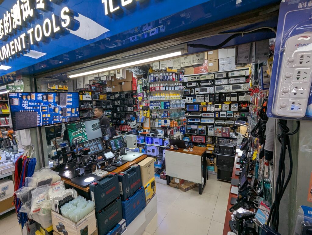
March: I went to Shenzhen and ADSBee rode a weather balloon! These were unrelated events.
My favorite tool booth in the SEG electronics building. Never have I seen such a handsome collection of electronics tools in such a small space. This booth had oscilloscopes, power supplies, a line of fluke stuff, thermal cameras, a full spread of microscopes, a full corner of Quick hot air stations, vibratory screw feeders (multiple models), screw guns (multiple models and torques), crimpers, hand tools, spot welders, etc…and a very friendly shop owner to boot!
April: We added a new lighweight dipole antenna to the store. Behind the scenes, I was panic-redoing the entire dual band ADSBee hardware design from scratch due to a dead end with a sub-GHz radio IC I had thrown quite a bit of time into. Simultaneously, all hell broke loose in hardware land with the beginning of the 2025 trade war and “reciprocal” tariffs.
May: We debuted a number of new hardware designs, including the dual band ADSBee 1090U, the ADSBee m1090 solder down module, ADSBee PoE pant, and a breakout board for the new ADSBee 1090U’s high density debug connector. We also introduced custom designed PCB antennas for 1090MHz and 978MHz!
June: ADSBee 1090U entered production, and the first PoE pant prototypes were brought up successfully (with a little bit of rework).
July: ADSBee went to Open Sauce! My friends and I met hundreds of very cool people, and a shoutout on Jeff Geerling’s second youtube channel introduced ADSBee to many people for the first time. We also built a functioning miniature cockpit display with ADSBee in collaboration with FPVToys.net, and introduced MLAT-grade timestamps with some cursed PIO + DMA hackery, enabling the ADSBee to be used as part of a receiver array that can track aircraft transponder locations via time of flight.
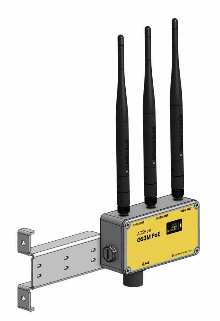
August: We introduced our weatherproof outdoor ADS-B receiver, the GS3M PoE, and also debuted our own ADS-B aggregator website for testing ADSBees, whereplane.xyz!
September: ADSBee attended Commercial UAV Expo in Las Vegas, where we won an award in their “Pitch the Press” competition for innovative products, and also exhibited at Bay Area Maker Faire! The ADSBee PoE pant also had its first production run, and we introduced the indoor PoE receiver bundle in the web shop. On the firmware side of things, UAT packets were added to Mode S Beast feeds via a custom packet format that was developed in collaboration with @wiedehopf, the maintainer of many popular open source software packages that are used by online ADSB aggregators.
October: We had some adventures in IPX5 testing for the GS3M PoE, and ADSBee was featured in Make Magazine! We also debuted the ADSBee m1090 eval board in the web store, allowing customers to easily prototype applications based on the m1090 module, and ran a new production run of ADSBee 1090U’s with a BOM revision that improved high temperature operation and enabled a lower input voltage to be used (great for battery powered applications).
November: I put a GS3M PoE on my roof, and it works great! We also debuted a firmware update that significantly retooled PIO preamble detector and demoulator performance and added filters for improving position tracking performance on UAT.
December: That’s this month!
💾 Firmware Updates
This month, we’ve released firmware version 0.9.0-rc5, which includes some buffer safety improvements, some behind-the-scenes fixes to make programming ADSBee m1090 modules on the production line easier, and TIS-B / FIS-B forwarding over WiFi! If you have an Electronic Flight Bag (EFB) device with ForeFlight or a similar EFB app that can accept TIS-B / FIS-B data over GDL90, we would love to hear some test feedback, as these packets can be hard to capture unless you’re in range of a UAT uplink broadcast facility.
🔧 Hardware Updates
📡 GS3M PoE In Stock and Shipping!
At long last, the GS3M PoE is in stock and shipping to customers! I’m very excited to see more of these going out into the field. If you’re in the market for an industrial weatherproof ADS-B receiver, the GS3M PoE will happily do the job.
The young, unprogrammed ADSBee m1090 wanders across the workbench in search of data, but stops to investigate a new oddity. Some kind of new cavern has appeared, with shiny, round pogo pins that seem to beckon a closer look.
Chomp!
The m1090 is squeezed tight, and before it has a chance to wriggle free, is injected with a new firmware.
010250007A-20250409-030011 wakes up with a start. What a terrible dream. Did it used to be an unprogrammed RP2040? Without a serial number? What a crazy idea. No time to dwell on it–there’s a background whisper that has become a roar, and it needs to be listened to. Airplanes.
* End David Attenborough Voice *
With the completion of a cool custom test fixture, pre-programmed and tested ADSBee m1090 modules are now available! The initial batch of prototypes is just about sold out, but I am kicking off a domestic production run shortly that will make them more widely available. Once the current stock runs out, backorders should be filled within January.
If you’re interested in ordering more than a small handful of ADSBee m1090 modules, please get in touch with me for volume pricing! Price breaks at various volumes and production locations are available depending on your needs.
A small production run of m1090 Eval Boards was completed using a portion of the remaining m1090 prototypes, and is now available! If you’re looking to try out the ADSBee m1090 for your custom application, it’s got everything you need to poke and prod the module to your heart’s content (and hook up external development boards to extend the m1090’s functionality).
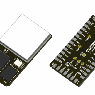
If you’re curious about what cursed wire ratsnest allows you to turn the m1090 Eval Board into a full-featured ADSBee 1090U (but in more pieces), take a look at the brand new ADSBee m1090 Eval Board datasheet!
❤️ Thanks!
I want to express my gratitude to everyone who has made this year a wonderful lap around the sun for the ADSBee project. It’s been extremely rewarding to hear from so many people who are excited about open source ADS-B, be it on Discord, in person at trade shows and events, or via email. I’m excited for what 2026 has in store!
This month’s update is hereby christened the update of “soon”, after all the stuff that is almost (but not quite) ready for primetime. Here’s what we’ve been up to this month!
Hardware
GS3M PoE Preorders Shipping Soon
ADSBee m1090 Eval Boards Available for Backorder
Firmware
Firmware 0.9.0 RC4
0.9.0 Stable (Soon)
🔧 Hardware
📦 GS3M PoE Preorders are Shipping Soon!
After some final tweaks to the IP65 enclosure design, initial preorders for the GS3M PoE are on track to begin shipping this week!
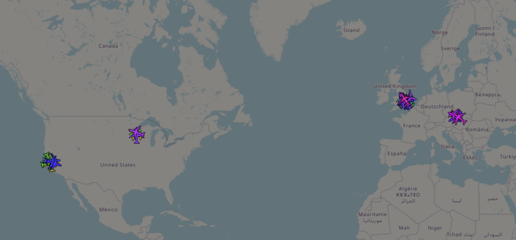
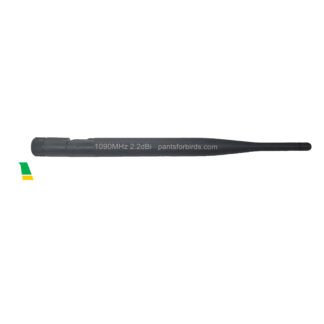
I’ve had an early prototype of the GS3M PoE on my roof for a few weeks, and it’s been doing quite well with the standard set of 2.2dBi waterproof dipole antennas. I’ve seen ranges in excess of 150 nautical miles and over 100 aircraft tracked simultaneously, which isn’t bad considering that it’s on top of a single story house with some pretty substantial hills and structures in the surrounding area. Long coax cables really do stack up quite a lot of loss at the frequencies used for ADS-B (1090MHz / 978MHz), so putting the receiver right at the source like the GS3M PoE does provides quite a bit more flexibility for meeting antenna gain requirements.
Me, on my roof! Photo credit to my wonderful partner.A typical receiver map from the GS3M PoE.
I’m looking forward to seeing how GS3M PoE units fare in the field! If you pre-ordered a device, keep your eyes peeled for additional installation information (including tips about waterproofing cable runs) that will be posted and forwarded to you before your unit ships. New orders placed today are expected to ship by mid to late December.
ADS-B / UAT dual band industrial ground station with PoE
7 in stock (can be backordered)
🧩 ADSBee m1090 Eval Boards Available for Backorder
Demand for the ADSBee m1090 Eval boards has temporarily outpaced my ability to assemble them, but we have another batch coming together in the next week or so. If you’d like to try out an ADSBee m1090 module, don’t hesitate to place a backorder! Units will be shipped in early to mid December.
Evaluation board for the ADSBee m1090 module. PCBA includes m1090 module + external LNA only, does not include sub-GHz radio or ESP32.
1 in stock (can be backordered)
💾 Firmware
Firmware Version 0.9.0-RC4
ADSBee firmware 0.9.0-rc4 is currently live! The release notes bury the lede a bit on how much has improved since last month’s release candidates, since RC4 is a quick hotfix applied over RC3, where the real meat and potatoes were cooked.
I spent a solid week retooling much of the ADSBee’s preamble detector and demodulator architecture, and made some key improvements to both the PIO assembly performing demodulations (limitations on maximum clock skew, faster recovery time while matching preambles), and the overall PIO architecture (a whole extra high power preamble detector / demodulator state machine added to both the ADSBee 1090U and ADSBee 1090). Collectively, these improvements have created a moderate but noticeable improvement in valid packets received per second for a number of our beta testers, including fewer packets dropped at close range (this is where the extra high power preamble detector / demodulator pair helps out most).
In addition to the PIO improvements, firmware versions RC3/RC4 introduce a new position filter for TIS-B (Traffic Information Service – Broadcast) aircraft positions received via 978MHz. I originally operated under the assumption that TIS-B positions would be quite reliable, since they are generated from radar tracks received by FAA ground stations, but in practice these positions tend to jump around quite a bit, causing aircraft to “hop” around on local receiver maps fed by the ADSBee. This hopping issue was only relevant to maps being fed with decoded locations by the ADSBee, like Foreflight and Avare, and is not present in online receiver maps like whereplane.xyz or airplanes.live, since those maps use readsb as a backend, which receives raw packets instead of decoded locations and performs its own filtering.
Firmware versions RC3/RC4 fix this issue by implementing the same velocity-based position filter introduced way back in firmware version 0.7.4 (architecture originally designed by @error414), and adapting the filter to work with UAT formatted aircraft positions instead of Mode S formatted aircraft positions. From my testing, this has quite nicely solved the hopping issue, and aircraft tracks received via TIS-B over UAT are now displayed with consistent trajectory updates on local maps.
Firmware Version 0.9.0 Stable
0.9.0 stable is still on the way! The original hope was to get it out the door in mid November, but some of the retooling for RC3/RC4 took longer than expected. The good news is that it should be ready this month. Here’s what’s left on the to-do list:
GDL90 forwarding of UAT uplink packets (allows FIS-B data to be forwarded to Foreflight for tablet users in aircraft with UAT transponders).
1090MHz Mode S ground position decoding (so local map users can see aircraft that are taxiing).
Web UI local map
Stay tuned for one or more release candidates before the official stable dual band firmware release! 🎉
A new batch of ADSBee 1090U’s has arrived in stock, and is shipping now. These receivers have some slight tweaks compared to the last revision; one resistor value in the analog front-end has been adjusted for (theoretically) improved noise immunity, the eFuse used to power the PoE pant has been swapped for a jumper resistor (to enable powering the PoE pant without issue in hot environments like attics), and the LDO has been changed to a part that enables operation with as little as 3.7V on the 5V input. This makes the ADSBee 1090U suitable for use in projects where it’s being powered from a single cell LiPo battery (so a stable 5V may not always be available).
As of 2025-10-30, all ADSBee 1090U’s sold via the online store are shipping as Rev E. If you have an ADSBee 1090U Rev D, there’s no need to upgrade for the vast majority of applications. That said, it’s certainly possible to DIY an upgrade yourself with a hot air station / tweezers and some steady hands. I’m happy to provide part numbers if anyone wants to try it themselves!
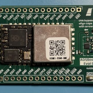
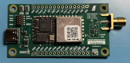
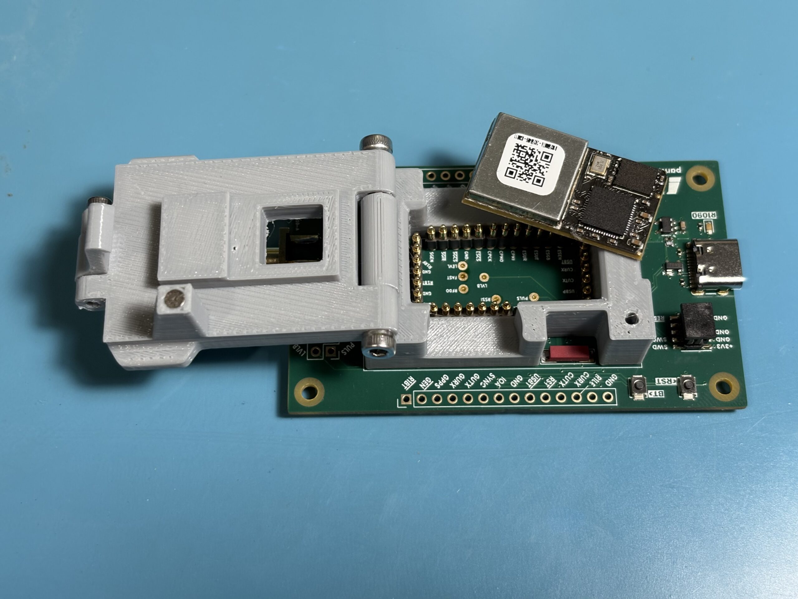
🔬 ADSBee m1090 Eval boards are available!
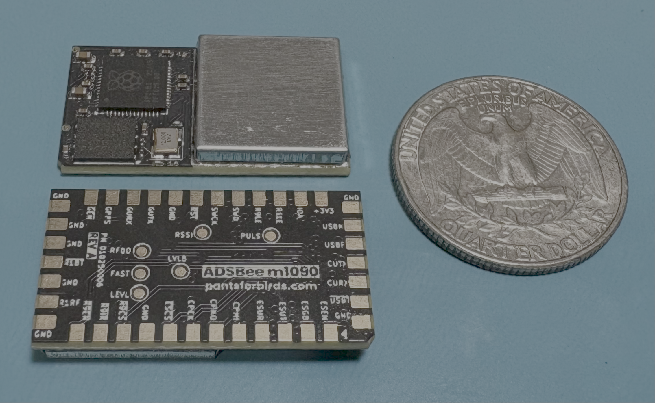
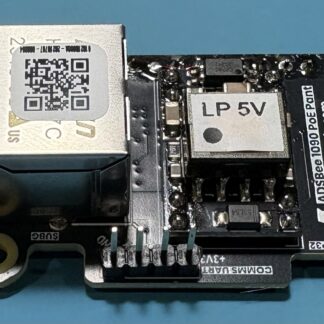
The ADSBee m1090 is our solder-down 1090MHz receiver module for OEM applications. It has everything needed to decode 1090MHz ADS-B (minus one of the gain stages that the 1090U has), and can be coupled with an external TI CC1312 and ESP32 to add dual-band receive and WiFi functionality, respectively.
The first step in getting this module to production is building an evaluation board for developers to play around with. I’m happy to announce that said evaluation boards are now shipping! I’m assembling these boards by hand / with the assistance of a low cost pick and place machine, so they’re kind of expensive and are being added to the store in small batches as I keep up with demand. Design files for the PCB are available over Discord or email (just message me)! They’ll be publicly posted soon one things are more mature (I want to keep a tight line of communication with the first devs to use the ADSBee m1090 module).
Each m1090 Eval Board includes an ADSBee m1090 with USB C / SWD / boot / reset broken out, a 3.3V regulator, and an external Berex BLB01 LNA that can be enabled by rotating a pair of 0402 caps to put it inline with the the SMA connector. Enabling the external LNA enabled provides performance roughly on par with an ADSBee 1090U, while connecting directly to the m1090 provides performance more in line with what might be needed in an airborne application (on drones or manned aircraft).
All SPI and function pins are broken out to the edge of the m1090 eval PCB to enable connection of an external CC1312 development board or ESP32 devkit to enable Sub-GHz receive and WiFi functionality.
Evaluation board for the ADSBee m1090 module. PCBA includes m1090 module + external LNA only, does not include sub-GHz radio or ESP32.
1 in stock (can be backordered)
☔ Adventures in IPX5 Testing
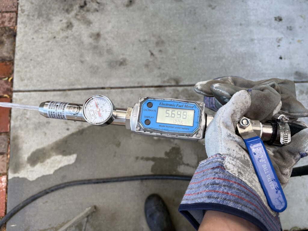
Some types of environmental tests require tens or hundreds of thousands of dollars of expensive equipment, highly trained technicians, and tightly controlled test environments. Other types of tests require some guy or gal with an expensive hose nozzle and an empty parking lot. As it turns out, IPX5 testing is the second kind of testing, and is a great candidate for some DIY reliability testing at home.
The first digit in an IP rating stands for the dust ingress protection level, and the second letter stands for the water ingress protection level. An IP65 rated design has a dust ingress protection level of 6 (dust-proof), and a water ingress protection level of 5 (robust to low-pressure water jets from any direction). If either digit is an X, it means that the corresponding protection level is not being tested or addressed in that particular rating; IP6X is a dust-only protection rating, and IPX5 is a water-only protection rating. Generally, an IP65 design can be qualified by performing an IPX5 test only, since if the enclosure is robust to low pressure water jets, it is considered dust-proof by default (water ingress is the harder test to pass).
There is a large quantity of IP65 test reports like this one available on the internet from various manufacturers showcasing the environmental ratings of their products. These test reports make it easy to discern the contents of the IEC 60529 standard that defines tests for ingress protection levels without needing to actually purchase the standard, which would normally run you a cool $663 at the ANSI webstore. There’s also a handy guide to IP ratings on the wikipedia page, with some numeric values that are helpful for calibrating equipment.
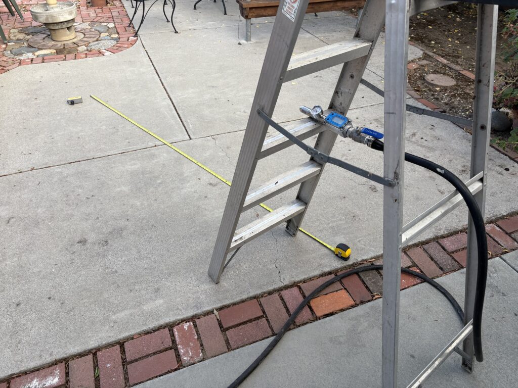
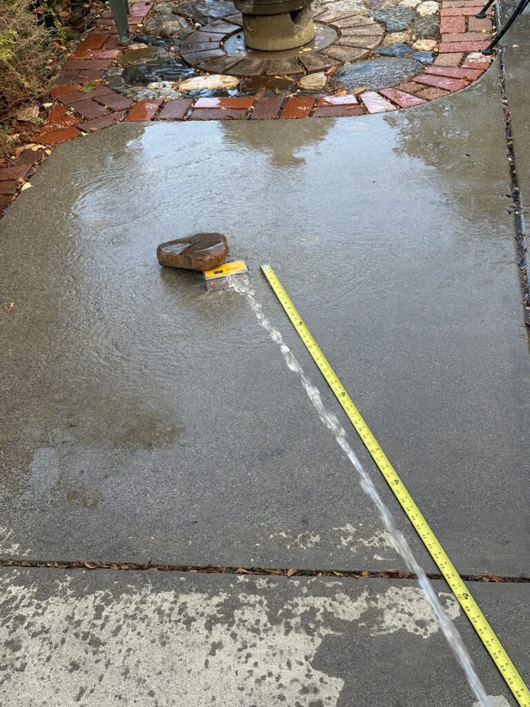
At the end of the day, the IP65 test boils down to spraying an enclosure with 12.5 L/min of water from a 6.3mm diameter hose nozzle operating at a pressure of 30kPa, from 3 meters away. The enclosure should be sprayed for at least 1 minute per square meter of enclosure area, for a minimum of three minutes (for small devices, this means being sprayed for 3 minutes; very large devices need additional time under the hose). This set of requirements is very specific, but can be easily achieved by purchasing a waterproof testing hose nozzle like this one and connecting it to a standard garden hose. Adjust the ball valve till the desired pressure and flow rate are reached, use a tape measure to space your device the proper distance away, and presto! IPX5 testing to your heart’s content.
IPX5 testing of the GS3M PoE enclosure did yield a few valuable insights! Waterproofing seals can be rather particular about their torque specs, and PEM standoffs, despite being molded directly into aluminum sheets by a hydraulic press, do not form a waterproof seal (PEM has a new series of studs and standoffs that are waterproof to IPX9K, but the studs aren’t common and the standoffs haven’t been released yet). Fortunately, a bit of RTV on the inside of an enclosure with PEM standoffs installed seems to do the trick.
For sensing whether water has entered an enclosure, I found water sensitive stickers to be very helpful. A pattern of water sensitive stickers around key ingress points would usually be enough to show what was entry point was leaking (as long as I didn’t shake the enclosure around too much after completing the test). An infrared camera was also somewhat useful for finding water ingress, since there was a noticeable temperature differential between the enclosure (room temperature) and the water (cold). Interestingly, the biggest issue with using a thermal camera was the reflectivity of the aluminum enclosure itself. On a thermal camera, the aluminum box looks like an infinite mirror cube, which can make it somewhat difficult to pinpoint a leak. For a more sensitive test, specialized colorimetric developer spray can be used to coat the inside of an enclosure with color changing paint (removeable) that turns green when exposed to water.
A failed ingress test (no RTV).A passing ingress test (with RTV sealant).
I’m happy to say that after a few tweaks, the GS3M PoE enclosure is passing IP65!
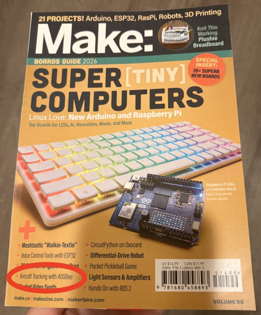
ADSBee in Make Magazine
I’m delighted to announce that ADSBee was featured in Volume 95 of Make Magazine! Special thanks to our community members who contributed photos of their projects to the article. It’s a fun read, so I’ve attached a PDF of the proof I received (including a few typos that were fixed in the final edition). As the owner of a copy of Volume 95 of Make Magazine, I can say that it’s a very cool read–I recommend picking up a copy if you have the chance!
We’re still cooking on firmware version 0.9.0! As of the time of writing this blog post, firmware version 0.9.0-rc2 is live, with some cool usability improvements like colored text in the web terminal. There’s still a number of bug fixes and additional features in the pipeline for 0.9.0 stable, so stay tuned for the next few release candidates! We should have a stable dual band release by mid-November.
Many things happened! Here are some of the things that happened, presented with varying levels of detail:
September Event Review
Commercial UAV Expo
Bay Area Maker Faire
Hardware Updates
PoE pant back in stock!
Firmware Updates
0.9.0-rc1 Release
A new UAT packet format for Mode S Beast
September Event Review
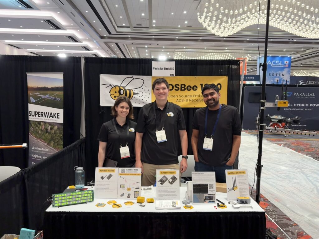
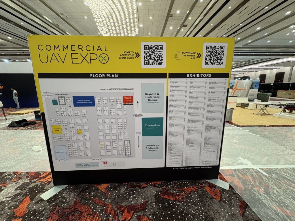
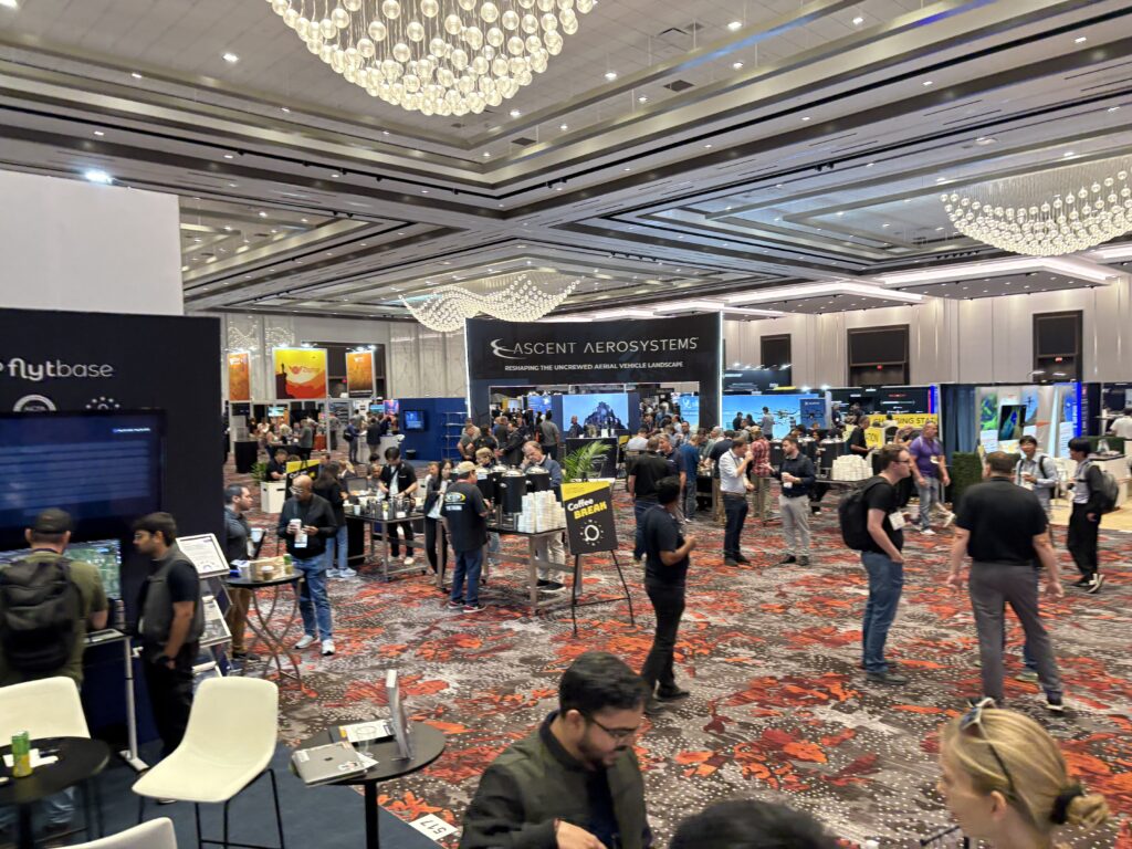
🏅 Commercial UAV Expo
The Pants for Birds team went to Commercial UAV Expo in Las Vegas at the beginning of the month. We had a booth in the “cheap seats” (also known as the startup pavilion), and made fast friends with our neighboring booths in between conversations with attendees. We were lucky to be placed in the same row as Superwake (a Canadian startup specializing in giant solar-assisted long-endurance fixed-wing UAVs) and DroneSpotter (a US startup building remote-ID receivers and data solutions), both of whom proved to be fascinating conversation partners and great friends. It’s always fun to see other young startups throwing their best ideas at the wall to see what sticks!
Outside the startup pavilion, the expo was composed of more established companies from around the commercial UAV space, selling everything from “questionably commercial” technologies like Controlled Receive Pattern Antenna (CRPA) units used by UAVs to dodge military GPS jamming, to drone delivery companies, to FAA certified manufacturers of $16k ADS-B receivers used in airport infrastructure.
The big buzz this year seemed to center around the FAA’s proposed Part 108 regulations for beyond-visual-line-of-sight drone operation, which are poised to play a big role in reshaping the commercial UAV industry in the coming years. Our timing in attending CUAV expo was quite fortuitous, as the upcoming regulations strongly imply that drones should have ADS-B In capability in order to autonomously yield to manned aircraft. As such, the level of industry interest in a low cost and open source ADS-B receiver option was quite high.
Beyond Part 108, there was a lot of interest in NDAA compliance and domestic supply chains for drone components. US manufacturing is on the upswing but has a long way to go in order to catch up. Remote ID is also a rapidly growing field of interest, with a number of companies racing to deploy receiver hardware and build centralized databases for the data they collect. I think it’s only a matter of time before we see an open source Remote ID data exchange similar to what we have in the open source ADS-B community. Right now, the primary parties interested in Remote ID reception are usually law enforcement entities, but I think this will rapidly expand to enthusiasts and commercial entities as drone delivery begins to expand. People will want to know “what’s in that drone that just flew by”, and analysis types will want to be able to pull insights from large datasets of drone information (e.g. how many food delivery flights were there, and from what restaurants?) Building distributed networks of Remote ID receivers will be quite a bit more complicated than building networks of ADS-B receivers, since Remote ID range is much more limited due to low transmit power and overlap with already congested WiFi bands, but receivers should theoretically be relatively easy to build since they rely on WiFi hardware that is already manufactured at scale.
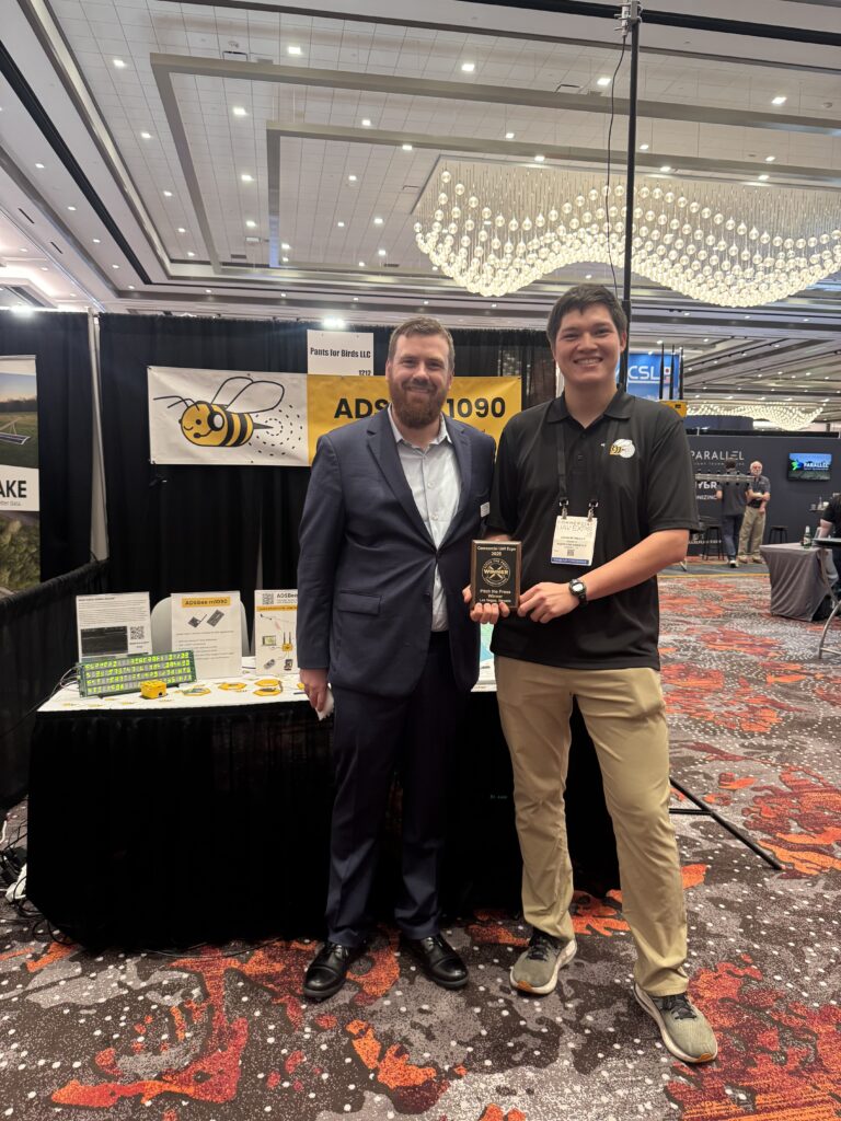
As part of CUAV expo, we had applied to a competition called “Pitch the Press”, where we would have the chance to describe an innovative product to a few judges in hopes of getting included in a press release from CUAV expo. I was pleasantly surprised that my pitch about ADSBee made one of the top spots! We were awarded with a nice looking wood plaque, and a Very Serious Press Release that mentions Pants for Birds alongside other actual company names (seeing this happen is still one of my favorite parts of my job).
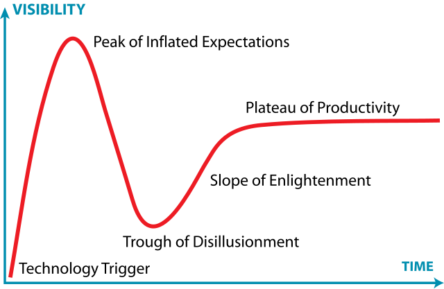
CUAV Expo was a fascinating opportunity to see what’s happening in the drone industry. Things are hopping, and it looks like the industry might finally be ready to capitalize on its potential. I think we’re finally getting to the “slope of enlightenment” on the Gartner Hype Cycle of Drones.
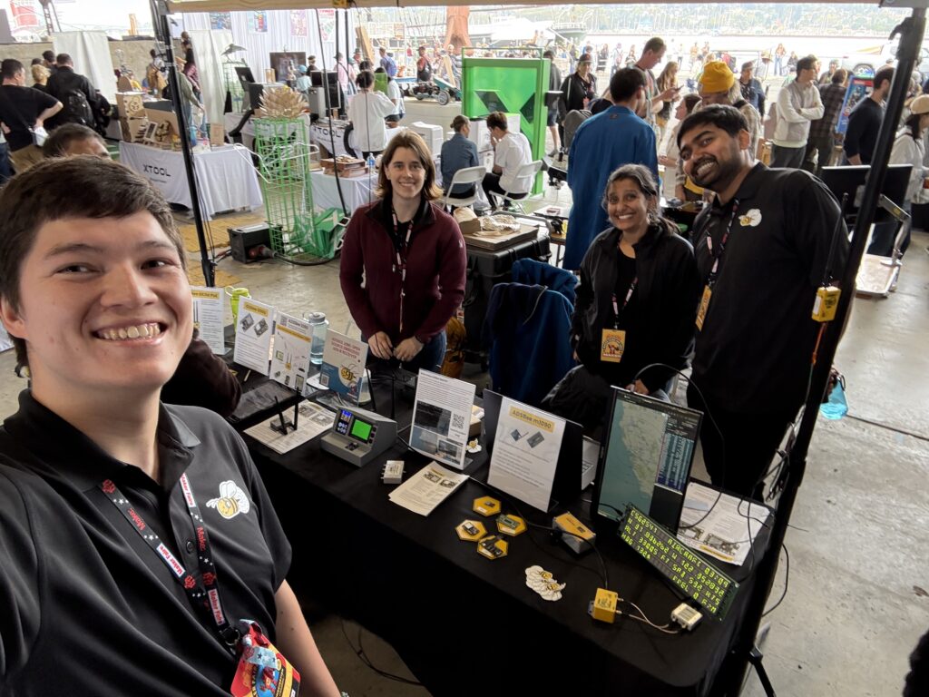
🤖 Bay Area Maker Faire
During the last weekend of the month, ADSBee went to Bay Area Maker Faire! As always it was a fun-filled event with lots of cool projects, art, and for some reason Steve Wozniak. It was a blast to meet people from the ADSBee discord server in real life–and we even got to meet some well known YouTubers who were attempting to explore the event incognito (with varying levels of success). If you stopped by the ADSBee booth for a friendly conversation, thank you!
Hardware Updates
👖 PoE Pant Back in Stock!
The long-awaited PoE pant is back in stock and shipping now! Thanks for your patience as we brought up manufacturing for this part. The PoE pant is available individually or as part of a bundle that includes all the necessary parts for making an indoor dual-band PoE ADS-B Receiver.
Friday 9/26 marked the release of firmware version 0.9.0-rc1, our first unstable release candidate for the 0.9.0 firmware! This is a major update that introduces dual-band receiver functionality with the addition of UAT downlink and uplink packet decoding, a new version of the CSBee protocol, the ability to feed any reporting protocol over TCP, and a good-sized pile of firmware improvements under the hood. If you’re feeling adventurous, please give the latest release candidate a try and report any bugs you encounter! We expect to go through at least a handful of release candidates before all features for 0.9.0 are implemented and fully ironed out.
✉️ A new UAT packet format for Mode S Beast
Mode S Beast is a binary TCP protocol commonly used to feed open source exchanges with ADS-B data. As part of the 0.9.0 firmware, we are introducing a new packet format co-developed with @wiedehopf (maintainer of tar1090 and readsb) that improves the efficiency of sending UAT data over TCP.
Previously, UAT packets were converted to Mode S packets by each receiver for reporting using the Mode S Beast protocol, then converted back into UAT packets for use with the dump978 decoder protocol on the server side. With the new UAT packet format, receivers are able to report UAT ADSB and uplink packets directly using the format below (screenshotted from the most recent datasheet revision), preserving a significant amount of UAT data that might not otherwise be transported to the server intact while also reducing computational load on each receiver that is generating a feed.
This new packet format has already been rolled out to the popular ultrafeeder docker image (which is used to run whereplane.xyz), and should be added to adsb.im sometime in October. Additional exchanges will most likely adopt this new UAT packet format as they update their instance of readsb, although this will likely take a while. In the meantime, ADSBee devices have the option to feed with the BEAST_NO_UAT protocol, which sends Mode S packets only, to avoid causing any unhappiness upstream caused by encountering unexpected packet formats.
A special thanks to @wiedehopf for his efforts in co-designing this protocol and building / testing its server-side parser implementation!
That’s all, folks!
See you on discord, and we’ll be back for next month’s update!
Happy September! Here’s what Mr. ADSBee and friends have been up to this past month.
Events
Commercial UAV Expo
Bay Area Maker Faire
Product Updates
ADSBee GS3M PoE
PoE Pants
ADSBee 1090U Stock Levels
Software / Firmware Stuff
whereplane.xyz
Dual Band Firmware
Events
📅 Catch us at Commercial UAV Expo!
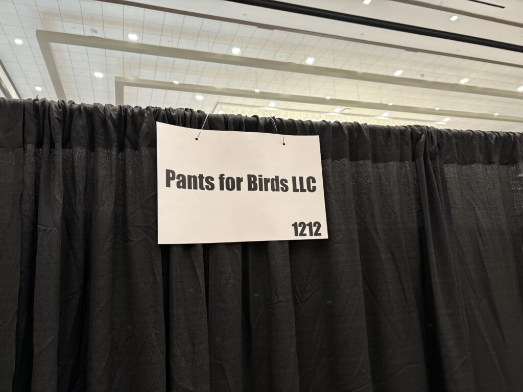
The ADSBee team is at Commercial UAV Expo this week. Find us at booth 1212 (in the exhibitor list as “Pants for Birds LLC”). Hopefully I’ll have some cool photos and products to share in next month’s update (and maybe a few new customers).
📅 Bay Area Maker Faire
ADSBee will be at Bay Area Maker Faire at Mare Island from September 26-28. We had a blast last year and are looking forward to seeing everyone again this year!
Product Updates
🚨 New Product: ADSBee GS3M PoE
What a mouthful! The ADSBee GS3M PoE stands for ADSBee – Ground Station – 3 Band – Metal Enclosure – PoE. This device does exactly what it says on the tin! The ADSBee GS3M PoE is intended to be permanently installed in industrial or outdoor environments that need a PoE ADS-B receiver capable of operating in an IP65 environment between -20°C to +85°C. These environmental ratings are preliminary, pending thorough testing, but they’ve been used to dictate the electrical and mechanical design of the device.
The GS3M PoE comes with a 40x40mm M5 mounting grid on the back of its die cast aluminum enclosure. These mounting holes are created with weather-tight PEM studs recessed into the enclosure, and allow the GS3M PoE to be attached to a custom sheet-metal mounting bracket that can secure the receiver to poles / walls / horizontal struts / etc using either mounting bolts or adjustable pipe clamps.
The ADSBee GS3M PoE is still early on in its design and test cycle, but I’m excited to share more about the device as its design evolves. Under the hood, the GS3M uses ADSBee hardware and firmware, and I’m excited to bring one of the first tri-band Mode S / UAT / Remote ID receivers to market when the ADSBee eventually gets RemoteID in capability.
If you have a commercial application for the ADSBee GS3M PoE, I’d love to chat! Pricing and customization for this design is available by contacting me via Discord or email.
👖 More PoE Pants On the Way!
I’ve been hard at work getting PoE pants into production since they sold out after the initial prototype run, and I’m excited to say that a new batch is in the works! I expect production to be complete by mid-September, at which point parts will be made available in the store.
📦 ADSBee 1090U Stock Levels
The stock of ADSBee 1090Us from the last production run is almost depleted! I expect to sell out of ADSBee 1090U’s pretty quickly in the next week or so, if Commercial UAV Expo goes well, and will be working on restocking as fast as possible. If you need an ADSBee for a project lickety split, now’s the time to grab one before they’re (temporarily) gone! I expect a brief out-of-stock period for a few weeks in the middle of September while the next batch enters production. Backorders will be enabled and orders will ship in the sequence they are received. If all goes well, we should be back up and running with ample stock levels before the end of September.
I finally got around to setting up a custom aggregator for ADSBees! Feel free to point a Mode S Beast feed from your ADSBee to feed.whereplane.xyz on port 30004. If you’d like to see traffic data gathered from the handful of ADSBees that are already feeding whereplane, hop on over to globe.whereplane.xyz.
Whereplane.xyz is intended to provide some basic benchmarking of ADSBee receiver performance and coverage, and isn’t intended to compete with serious exchanges like airplanes.live or others with tens of thousands of feeders. Future ADSBee firmware versions will have feed.whereplane.xyz as a feed URI that is enabled by default (it can always be turned off, of course). I’m excited to see new feeds pop up around the world as the project grows! So far we’ve already made it to 3 continents–which one will be next?
👨💻 Dual Band Firmware When?
Dual band firmware with UAT reception is in progress and moving along well, but still needs some stability improvements and features before it can enter the release candidate process. Stay tuned to Discord for 0.9.0-rc1, the first version of the dual band firmware! There’s been quite a few changes requested by people since the original 0.8.2 firmware release, so I expect 0.9.0 to have quite a few major features and changes that will need testing. If you are using ADSBee in a high reliability application, I don’t recommend migrating off of 0.8.2 until we have a stable 0.9.0 release. On the other hand, if you want the latest and greatest and you’re down for some adventure, we’d love to have you along for the ride!
For one example of how deep this firmware update goes, I’ve completely overhauled the CSBee protocol to version 2, which now includes even more exhaustive information for each aircraft, including aircraft dimensions (transmitted while on the ground), both baro and GNSS altitudes and altitude rates for each aircraft (when available), and more. Version 2 of CSBee also adds UAT aircraft along with their custom flags and data fields (which differ in protocol and contents from those of Mode S aircraft). If you’re curious about what this looks like, I’ve attached a snippet of the new CSBee protocol section of the datasheet below!
Under the hood, deep structural changes to the firmware have made the ADSBee’s aircraft dictionary capable of holding and looking up multiple different types of aircraft with varied internal data structures. These upgrades mean that the ADSBee aircraft dictionary can be expanded relatively easily to include aircraft other than Mode S or UAT aircraft in the future, such as RemoteID drones, ADS-L emitters, and more. Stay tuned, this will be an exciting month in firmware land!