Posted on Leave a comment

ADSBee 1090 December Update

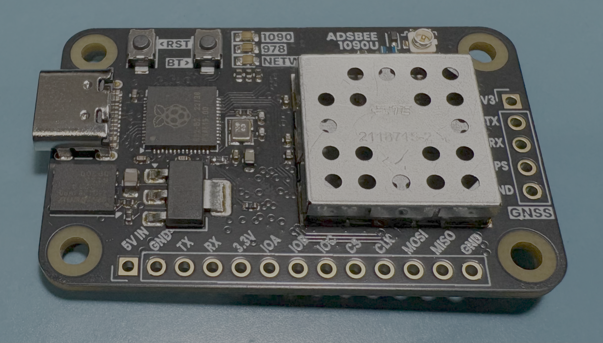
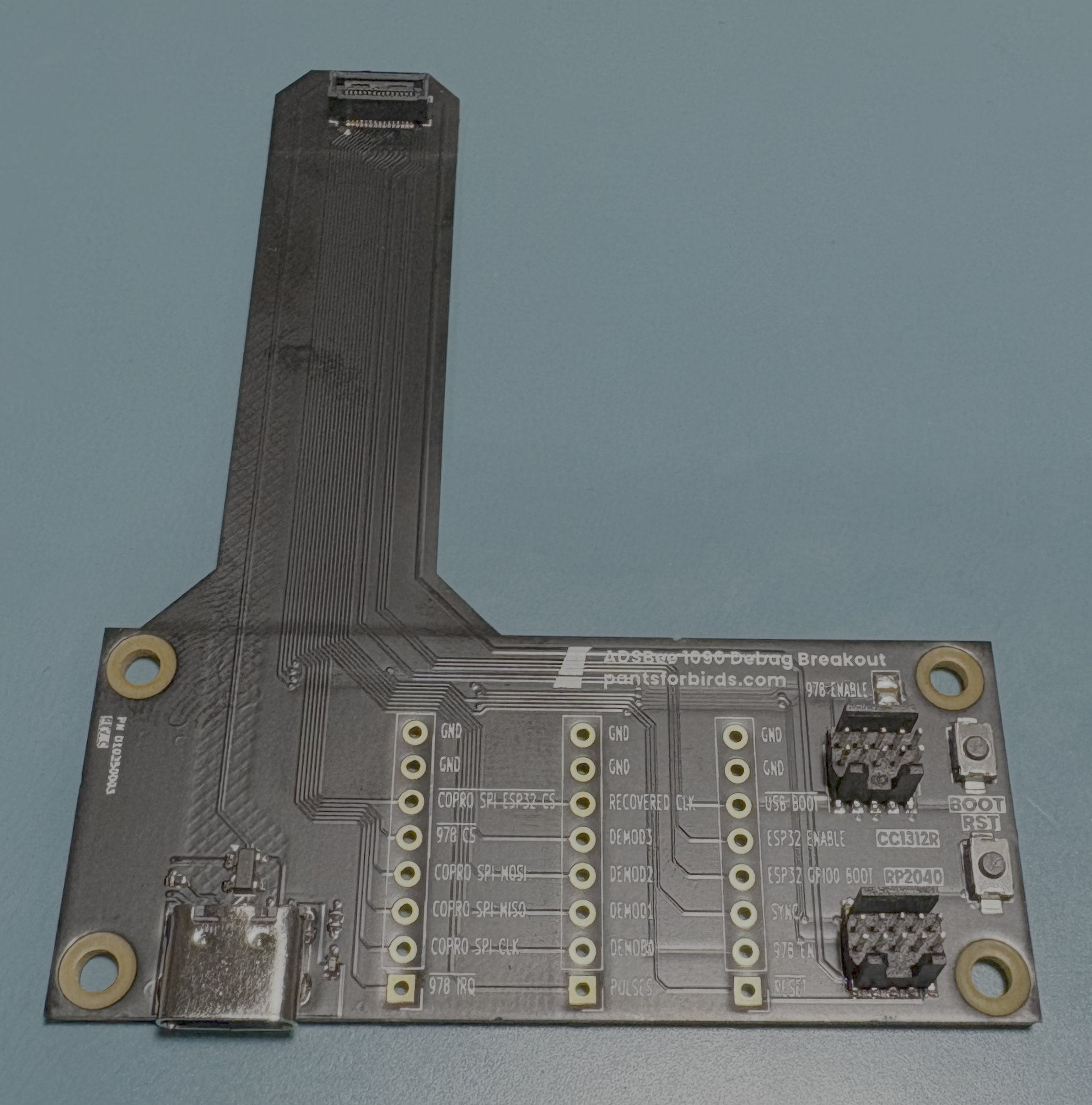
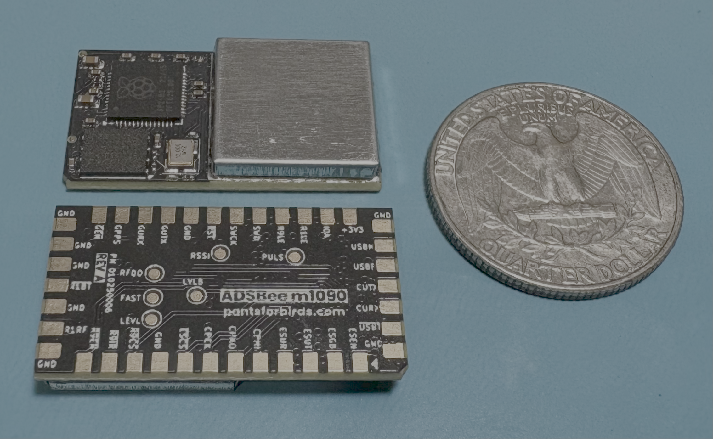
Happy almost-new-year! It’s been another busy month, with some solid firmware progress on the ADSBee 1090. This update contains some usual month-in-review information about newly released features, but also includes a bit of blab at the end about how OTA firmware updates work for ADSBee, as a treat!

  • Firmware Version 0.7.0
    • OTA firmware upgrade capability (experimental)
    • Network diagnostic and configuration features
    • ADSBee PyPi package
    • Ethernet support (very experimental)
  • Deep Dive: How do OTA firmware updates work for ADSBee?

Firmware Version 0.7.0

This month’s biggest milestone was the release of firmware version 0.7.0, which includes some much-awaited features that should be very welcome for network users of the ADSBee 1090!

OTA Firmware Upgrade Capability

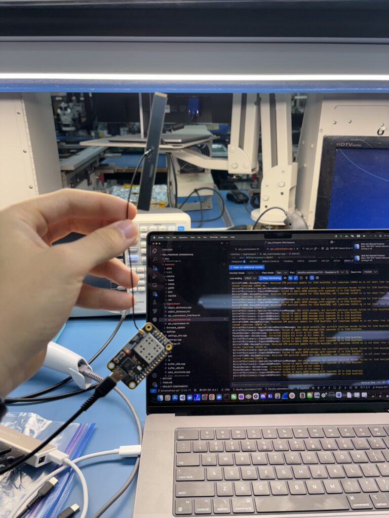
Since the initial inception of the ADSBee 1090, my intention has always been to make it easy to cram into small or generally difficult to access spaces (e.g. attics, boxes on roofs / trees, etc) that might have better ADSB reception than more accessible alternatives. There are a number of creative solutions available for getting power to these spaces in order to run an ADSBee, but until now it’s been generally inadvisable to put an ADSBee in said difficult-to-access spaces due to the need to physically access the device in order to upgrade firmware over USB.

With the release of firmware 0.7.0, users can now send firmware upgrades to their ADSBee 1090 remotely. Each firmware release after 0.7.0 will now include both the usual .uf2 file, for upgrading firmware over USB in DFU mode, and a new .ota file, which uses a custom file format to allow firmware binaries to be flashed over the network using a web browser or a Python script (more on the Python stuff later). This feature is still considered “experimental”, in that there are still a few bugs that can make a firmware upgrade fail under some circumstances, but the firmware and bootloader architecture of the ADSBee make it very resistant to “bricking” itself by attempting to boot an invalid firwmare image, since each firmware needs to pass a multi-step CRC check before it’s used. In all the cases that I have tested, a failed firmware upgrade (resulting from network disconnection, software bugs, or other issues) can be circumvented by attempting the upgrade again.

Network Diagnostic and Configuration Features

It’s now easier than ever to debug network connectivity issues on an ADSBee 1090 via the command line interface by using the new AT+NETWORK_INFO? AT command. ADSBees queried with this command will reply with the connection status of each of their network interfaces, as well as the IP and MAC address of all clients connected to their WiFi Access Point, if enabled.

ADSBee 1090’s can also have a custom hostname configured via the AT+HOSTNAME command. This is handy if you’d like to differentiate multiple ADSBee devices on your network, for instance one ADSBee 1090 can be named “adsbee-attic” while another might be labelled “adsbee-portable”. mDNS hasn’t been activated yet in ADSBee firmware, so hostnames can’t be used to ping ADSBee devices or navigate to their local webpages, but that’s coming soon!

ADSBee PyPi Package

If you enjoy Python scripting and have a fun project you’d like to integrate with an ADSBee, you’ll be pleased to learn that the ADSBee python library I originally wrote for programming and testing ADSBee 1090’s in production is now available as a PyPi package! Getting started is as simple as pip install adsbee. The library includes a number of utility functions for sending and receiving AT commands over serial or network connections, and also includes a function that can execute fully automated firmware updates over aforementioned serial or network connections.

The Python library is still in its infancy, and is pretty much an internal tool that I’ve just blasted into the public world with very little in the way of documentation. I’ll be improving features and documentation in future releases, but if you’d like to get started with it in the meantime, the functions are well commented and I’ll be happy to provide examples and guidance on Discord. The source code for the library can be found here: as always, PRs are welcomed!

Experimental Ethernet Support

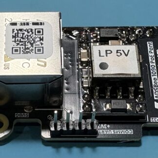
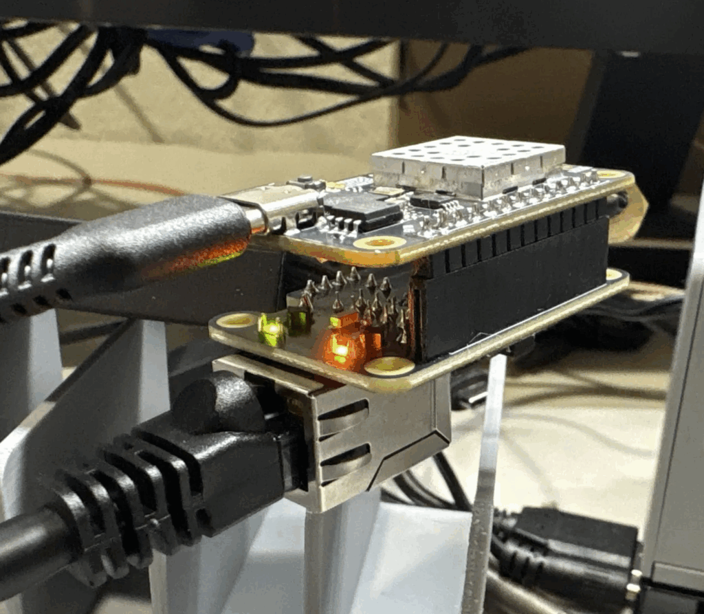
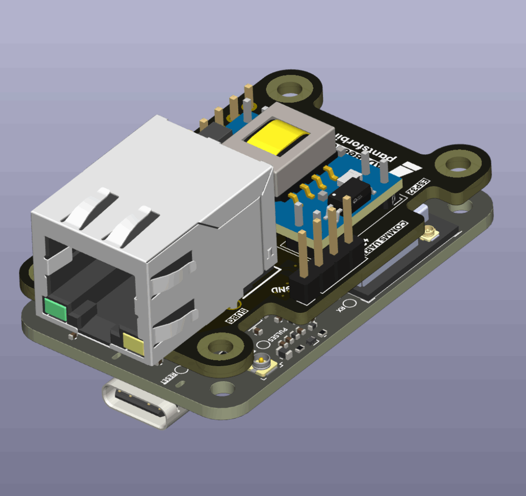
ADSBee 1090’s can now be connected to Ethernet! Although Ethernet connectivity isn’t yet reliable in all circumstances, devices connected to a W5500 Lite module as shown below can join a network, get assigned an IP address, and feed endpoints over the internet! Just be sure to enable the Ethernet interface with AT+ETHERNET=1.

Right now the Ethernet connectivity feature is a bit of an experiment, and isn’t considered “stable”. Future updates will focus on improving robustness and adding additional hardware and firmware features for Ethernet connectivity. Stay tuned!

How do OTA Firmware Updates work for ADSBee?

Updating firmware on an embedded device can be a bit tricky, since allowing firmware to update itself inevitably leads to the possibility that a device may update itself with the wrong firmware, or put the right firmware in the wrong place, leading to an unbootable or unusable configuration known colloqually as a “bricked” device.

In order to avoid this scenario, embedded devices like ADSBee that are being updated Over The Air (OTA) typically follow a few rules (well, probably a lot of rules, but here’s two that I know are important):

  1. Don’t update the code that is currently being executed.
  2. Don’t execute code unless it’s been verified to be correct.

Don’t update the code that is currently being executed.

Rule #1 seems obvious, since rewriting the very code that you are executing can lead to some problematic behavior. Typically rule #1 is accomplished by having either a factory-flashed bootloader that is in charge of updating applications and is never updated itself after leaving the factory, or with a system of multiple firmware partitions that can update each other.

The factory-flashed bootloader method is what’s currently used when ADSBee devices are updated over USB using the USB DFU (Device Firmware Upgrade) method. A bootloader has been permanently programmed into the ROM of the RP2040 during manufacturing on the Raspberry Pi Foundation’s production line, and this bootloader is capable of receiving .uf2-formatted firmware binaries over USB and programming them into the flash memory attached to the RP2040.

The downside of the factory-flashed bootloader method is that once this bootloader is installed, there’s no going back. Whatever protocol was programmed into the bootloader for updating device firmware will be the protocol that is used until the end of time for updating the product with new firmware. In the case of things like network firmware updates, which can be more complex and may be expanded with additional features over time, having a bootloader that’s frozen in time can become a problem as the software on the rest of the system evolves. Since ADSBee 1090 is intended to be delivered to beta customers half-baked and iterated on to fix bugs and fulfill newly discovered feature requests, I chose to implement the multi-partition firmware update method instead.

An ADSBee 1090 is kind of like a sleeping whale.

According to my google search results, unlike snails, whales are widely understood to sleep more than three. To my knowledge, many other mammals, like humans, are not very good at sleeping underwater (or perhaps more accurately, waking up after going to sleep underwater). How does a whale sleep without drowning?

Apparently, whales have a nifty trick up their sleeve. Whales can sleep one hemisphere of their brain at a time, allowing the other hemisphere to stay aware of the whale’s surroundings and move to the surface to breathe. Whale sleep behaviors vary between species, but whales can generally sleep while swimming slowly, or while bobbing around near the surface nearly motionless, like the sperm whales that are doing a great log impression in the image above (credit to Scientific American for the pic).

Much like a sleepy whale, the ADSBee’s firmware storage is divided into two application sectors, called FLASH_APP0 and FLASH_APP1. Each sector is identical in size and can store just under 8MB of code. When firmware in FLASH_APP0 is executed, it has access to the APP1 sector and can happily erase, write, and read firmware in that sector to its hearts content. Conversely, when firmware in FLASH_APP1 is executed, it has access to the FLASH_APP0 sector and can erase / read / write firmware in that section of storage without risk of overwriting itself.

When a firmware update is initiated, the application that is currently running on the ADSBee 1090 receives a firmware image that it writes into the complementary flash sector. Once this newly written firmware is verified to be correct, the microcontroller can “jump” into the new sector to begin executing that code.

There’s one piece of the puzzle remaining: when the ADSBee first boots up, how do we know which section to jump into first? This is where the FLASH_BL region comes in. FLASH_BL contains a very small bootloader whose only job is to check which partition was flashed most recently, and whether said partition is valid. If a partition is freshly flashed and is properly verified, the bootloader picks that partition to jump into. If a partition is freshly flashed but fails checksum verification, the bootloader falls back to the older firmware in the complementary partition.

Don’t execute code unless it’s verified to be correct.

Like billions of devices around the world, ADSBee 1090 relies on Cyclic Redundancy Checks to verify that chunks of firmware images being sent over the air, and complete firmware images, are correct (i.e. no bit flips introduced in transit, or other errors). Each chunk of data transferred over the air includes a CRC32 calculated over its bytes that is used to verify the integrity of the received data packet and corresponding chunk of firmware programmed in flash. Likewise, each firmware partition is pre-pended in flash with a binary header that indicates the status of the firmware partition and includes a CRC32 value for verifying its contents. Using these CRC values, the ADSBee is able to confirm that bits haven’t been flipped during transit, and that they have been programmed to flash successfully, before executing a newly flashed firmware image.

What are the steps to an OTA update?

OTA updates are a bit of a song and dance, with a few commands for putting the ADSBee into a firmware update mode, and then a bidirectional transmit and reply process used for sending the firmware binary in chunks over the serial connection normally used for AT commands.

Before any data chunks can start flying, it all starts with a .ota file. The .ota file is a new file format I invented, probably out of a lack of understanding of existing solutions, for flashing the ADSBee. Each .ota file contains two verisons of the firmware. One version is compiled for FLASH_APP0, and one is compiled for FLASH_APP1. This is a bit of a kludge, but was necessary since ARM M0+ cores don’t support Position Independent Code (code that can be run without a knowledge of where it is in flash).

Enjoy this screenshot from the firmware reference guide that I wrote! Note that in this case, we only have two applications, but the .ota file format is generalizable to an arbitrary number of application sectors.

Once an ADSBee-flashing program has read in the .ota file, the next step is to tell the ADSBee to enter a firmware update mode and then send over the relevant chunks of data. This is done over the AT command interface using the procedure below.

And that’s about it! Right now there are two programs written for updating ADSBee 1090’s over the air. One is written into the adsbee python library, and one is baked into the ADSBee 1090’s own webpage as a javascript application, allowing firmware images to be uploaded directly from any web browser. Updating firmware over the air currently takes just under 2 minutes (most of this time is spent erasing and writing flash, which seems to be quite slow). I’m sure there’s some additional optimizations that can be made to speed things up further; if you have any cool ideas about updating firmware (or see something that I goofed in my OTA process), I’d love to hear from you!

Acknowledgements

Many thanks to Brian Starkey for his excellent writeup of a similar Pi Pico bootloader project, which was a useful reference when implementing my own bootloader.

Hunter Adams also has a fantastic bootloader for the Pico that served as additional inspiration for my implementation.

Both of the aforementioned sources focused on bootloaders with a single application partition, but nevertheless contained many of valuable tidbits that came in handy when developing my multi-partition bootloader!

🎊Here’s to 2025! 🎊

It’s been a fantastic year on the ADSBee project! In just around 6 months this project has gone from a janky little prototype sitting on my workbench, to a janky little product sitting in homes around the USA, and around the world (as far away as Ireland and Australia)! Thanks for following along and making this project worth working on. Stay tuned, there’s lots more to come!

Posted on Leave a comment

ADSBee 1090 November Update

Happy post-Thanksgiving! Here’s what we’ve been up to this month.

TL; DR

  • ADSBee 1090 preorders are 100% shipped!
  • Documentation
  • Huge firmware update (0.6.2)

ADSBee 1090 Preorders 100% Shipped 📦🚀

All ADSBee 1090 preorders have been shipped, and should be arriving shortly! Many beta testers have already had a chance to try out their devices, and a number of them are currently feeding aggregator sites like airplanes.live and adsb.fi.

As of the time of writing, new orders for the ADSBee 1090 Beta Kit ship in 1-2 business days.

Some ADSBee 1090’s being programmed and tested before shipping.

Documentation 📄

Documentation for the ADSBee 1090 has been updated and improved! There’s now a quick-start guide with details about how to set up and configure an ADSBee, and the datasheet has been updated with a comprehensive description of all of the available AT commands.

ADSBee 1090 Firmware 0.6.2 💻

Besides shipping devices, most of my time this month was dedicated to a significant firmware update, which is now released as firmware version 0.6.2. This update includes a wide range of new firmware features and bug fixes. The full list of new features is available in the release notes, but I’ll go over two big ones here!

ADSBee 1090 Web UI

The most visible new feature is the web UI hosted by the ADSBee 1090’s ESP32 module. At the top of the page, a simulated terminal window allows direct input of AT commands to the ADSBee 1090’s command line interface, providing an easy way to interact with the ADSBee 1090’s configuration capabilities over a network connection. The bottom section of the UI includes a dashboard which presents metrics about how packets are being decoded, as well as information about currently active feeds.

The Web UI can be accessed by visiting the ADSBee’s IP address (192.168.4.1) on its self-hosted WiFi network, or by visiting its assigned IP address on an external WiFi network (you’ll need to instruct the ADSBee to join the network first using the serial command line interface).

Not-So-Secret Feature: because the console on the web UI is implemented as a WebSocket, you can connect to it from any device on the network by opening a WebSocket targeted to ws://<ADSBee IP address>/console. Happy hacking!

Mode S Beast Feeding

The ADSBee 1090’s Mode S Beast feed capability is just beginning to stretch its legs! ADSBee can now feed arbitrary IP addresses (e.g. 192.168.1.103) and DNS addresses (e.g. feed.adsb.fi) with demodulated Mode S packets in Mode S Beast format. Feed URIs and ports can be configured via the `AT+FEED` command.

What’s Next? 🔮

Upcoming Firmware Features

Here are a few major firmware features that I’m actively working on, or will be working on shortly! If you’d like to request features and bugfixes, please open or comment on an issue in the GitHub repository! Engagement is always appreciated, and issues let me prioritize what features are needed the most urgently.

If you are interested in contributing to any of these features (or others), please get in touch via Discord! Pull requests are always welcomed–let’s harness the power of open source together. 🌈📈

Network Bootloader

I’m currently developing a network bootloader which will allow users to update the firmware on their ADSBee remotely. This will be especially useful for anyone who wants to put their ADSBee somewhere less easily accessible, e.g. an attic space or a tree! Implementing this network bootloader is a bit of a complicated task that has been at least a month in the making, with some cursed adventures in linker files and CMake dependencies along the way. Fortunately, things are shaping up nicely, and it should be ready for (experimental) release soon!

Ethernet Support

The hardware on ADSBee 1090 has been designed from the beginning with Ethernet support in mind. The software driver for a W5500 Ethernet IC has been already been baked into the firmware on the ESP32, so in theory it shouldn’t be too hard to whack a proper Ethernet driver into the firmware and get something working with some janky hookup wire and a W5500 Lite module. Combined with a USB C PoE splitter, this could let users install their ADSBee 1090 in any PoE accessible location! Stay tuned for some fun prototyping on Discord. As long as I haven’t absolutely goofed some pinouts on the ESP32, we should be able to put together something that works!

Checksum Correction

One of the primary inhibitors of ADSBee 1090 performance has been demodulated packets with invalid checksums. These packets may be a symptom of some algorithmic errors under the hood in PIO demodulation, or could be related to the analog response time of various parts of the electronic frontend of the ADSBee’s custom receiver. Either way, there seems to be a pretty substantial pile of packets laying around with very serviceable signal strength and signal quality metrics, which nonetheless don’t resolve to a valid checksum. I’m excited to dedicate some time to implementing CRC correction techniques to see if any of these packets can be recovered! I’m hopeful that analyzing bit flip locations within demodulated messages might also offer some clues about what’s causing the invalid decodes in the first place, to see if additional receiver improvements can be made.

Manufacturing Improvements

The ADSBee Beta’s purpose is to collect feedback and performance / reliability data ahead of mass production of ADSBee 1090 in Q1 of 2025. I’m spending a good deal of time putting together data systems and test fixtures to provide traceability for devices through the manufacturing process. These might be fun topics for a writeup or a video in the future!

In the meantime, a good deal of effort is being dedicated to improving yield with the current manufacturing run. Some components on the ADSBee 1090 have proven to be remarkably temperature sensitive, requiring tweaks to some parts of the assembly process and additional testing before each device is shipped. Manufacturing and reliability testing will be an increasingly large focus moving forward. If you have a Beta unit that exhibits any weird / unexpected hardware behaviors, please get in touch! I’m very eager to learn about any and all failure device failure modes, and will happily replace any hardware that has failed due to manufacturing defects.

Let’s send it!

I’m so excited to see what everyone does with their ADSBee! Join the party on Discord and tell us what you’re building with your receiver.

Posted on Leave a comment

ADSBee 1090 October Update

Welcome to the it’s-still-technically-just-barely-October update! It’s been a crazy month and we’re making great progress leading up to the shipment of ADSBee 1090 Beta units.

TL; DR

  • ADSBee 1090 Beta pre-orders launched!
  • Receiver performance improvements in hardware and firmware.
  • ESP32 network firmware features.
  • Field testing in cool places.
  • Beta PCBAs in manufacturing and test!

🎉🚀ADSBee 1090 Pre-Orders Launched!🚀🎉

ADSBee 1090 pre-orders were launched on October 4, and are now more than 50% sold out! I think that all of the beta testers on our waiting list have had the chance to place a pre-order by now, so I’m lifting the one-per-customer limit. If you have an interesting application for a handful of ADSBee 1090 beta kits, now’s your chance to go wild! Beta kits come fully assembled in a 3D-printed enclosure with a WiFi antenna (internal) and a 1090MHz antenna (external). Preorders ship in Early November™ (I’m counting anything before November 14th at 11:59pm as “early November”).

Receiver Performance Improvements 🔧

Since the last update, there have been significant strides in receiver performance due to upgrades to both hardware and firmware on the ADSBee 1090. All of these changes have made it through to manufacturing, and I’m happy to report that ADSBee 1090 Beta units will be up to date with the latest and greatest aspects of the design! Three major improvements to the receiver design (two firmware, one hardware) are documented in the sections below.

Firmware Performance Improvement #1: Interleaved Preamble Detectors

ADSBee 1090 previously utilized a single PIO state machine for detecting message preambles and triggering the demodulator state machine. This was sufficient for good performance in most scenarios, but had a vulnerability in situations where noise pulses might trigger a high pulse just before the beginning of a valid preamble. The single preamble detector would ingest the stray noise pulse and begin its preamble search routine, and would thus still be in the midst of searching for the subsequent bits of a preamble when the first bits of an actual valid preamble would roll in. This could cause the preamble detector to miss valid preambles when they were preceded by some amount of noise.

The solution that I’ve implemented to address this issue is to have two preamble detectors operating simultaneously on separate state machines, in a round-robin sequence. Each preamble detector waits until the complementary preamble detector has already latched onto a rising edge before beginning its own preamble search, thus ensuring that the two preamble detectors don’t (usually) end up demodulating the same message. This means that the ADSBee 1090 can respond instantaneously to a rising edge with a preamble match routine, even if one of its preamble detectors is already occupied. This also adds a bit more wiggle-room for the preamble detector to perform its reset sequence after it aborts an invalid preamble match, as the complementary preamble detector is scanning for the next rising edge (previously, the ADSBee 1090 was completely blind to incoming preambles while its sole preamble detector was resetting).

In the oscilloscope screenshot below, we can see two interleaved preamble detectors triggering on messages (spikes on the blue trace, which shows raw RF power). The yellow trace corresponds to the first preamble detector, and the orange trace corresponds to the second preamble detector. The green trace shows the digital waveform being fed into the RP2040, which is being filtered for message preambles. We can see that there’s quite a bit of noise even when no message is present!

Hardware Performance Improvement: Analog Frontend Filter Capacitor Change

After more extensive evaluation of ADSBee 1090 Rev F’s performance on the bench and in the field in close proximity to aircraft, I discovered that it had significant difficulty with high power messages (e.g. messages from a close-by aircraft with a well aligned antenna radiation pattern). After a decent amount of debugging and poking at various parts of the receiver, I came to the conclusion that the additional gain stage on the ADSBee 1090 Rev F, which improved its overall receive range, was having the unfortunate effect of overloading the analog data slicer circuit in charge of converting RF power levels from the logarithmic power detector in the RF frontend into digital pulses being fed into the RP2040.

High power signals would present to the analog circuit as a high amplitude signal with a decently sized DC offset. The limited slew rate of the RC filter tasked with obtaining the centerline of the signal resulted in falling edges in the message preamble and start of the message failing to register, thereby leading to the ADSBee 1090 missing the message entirely.

The trace below shows a simulated aircraft message from a HackRF on the lab bench. RF power level is shown in orange, the filtered centerline of the power level is shown in blue, and the digital waveform output by the data slicer circuit is shown in yellow. Note that the preamble shape shown in yellow is incorrect, and the troughs between pulses don’t begin showing up correctly until a few bit periods into the message body. The incorrect preamble shape meant that the ADSBee 1090 wouldn’t trigger either of its preamble detectors, and the corrupted bits at the start of the message meant that even if a preamble detector had triggered, the message would have failed its checksum and been discarded.

The solution to this issue turned out to be relatively simple; the value of a single filter capacitor in the data slicer circuit needed to be adjusted in order to improve the rise time of the RC filter tracking the centerline of the RF power level. Dropping the value of a single capacitor from 1nF to 200pF resulted in a marked improvement to message demodulation capabilities with high power signals. The oscilloscope screenshot below shows a message demodulation from a live aircraft with the new 200pF filter capacitor. Note the increased responsiveness of the blue line to RF power levels!

Rework instructions have been released for upgrading from Rev F to Rev H (the rev of the PCB with the new filter capacitor value). These instructions are only meant for use by 1-2 hardcore early testers who received Rev F hardware and wanted to try out soldering themselves, but I’ve made the document public in case anyone is curious about what the upgrade procedure looks like. All ADSBee 1090 Beta Kits that are currently on preorder will ship as Rev H, so no need to worry about this part change if you haven’t received hardware already!

Firmware Performance Improvement #2: Dedicated High-Power Preamble Detector

Even with the improved responsiveness of the data slicer analog circuit provided by the upgrade to Rev H hardware, messages from very nearby aircraft were still being missed. While the improved responsiveness of the RF power level centerline RC filter meant that the message body was being demodulated correctly, the first pulse pair of the preamble sequence would occasionally blend into a single larger pulse due to the initial rise time required for the centerline filter capacitor to charge up to the DC offset presented by the message. This mangled preamble would be rejected by the ADSBee 1090’s preamble detector, causing the high-power message to be lost.

Further decreasing the value of the centerline filter capacitor proved to be impractical, as it resulted in additional noise in the message body that caused a degradation in receive rate for valid packets. Fortunately, I was able to further improve performance with decoding nearby aircraft messages by implementing a firmware improvement in the form of a third preamble detector dedicated to detecting mangled preambles from high-power transmissions. This preamble detector operates separately from the round-robin preamble detectors used for detecting well-formed preambles, and proved to be somewhat tricky to cram into the remaining state machine in the PIO peripherals. One unexpected bonus of this creative code stuffing exercise is that the GPIOA pin header on the ADSBee 1090 now serves as a “nearby aircraft” indicator pin, as it is used to transfer the demodulation interval pulses between the high power preamble detector and its corresponding demodulator state machine.

Message reception of nearby aircraft is greatly improved with the addition of the high-power preamble detector, allowing the ADSBee 1090 to demodulate packets from aircraft that are both very close to the receiver (<2 miles) and very far away (100+ miles) simultaneously. The packet receive rate for close-range aircraft still certainly has room for improvement, and may warrant further attention in the future. I’m excited to hear about user experiences during the Beta in a diverse range of operating conditions, as this will surely inform design decisions for the ADSBee 1090 firmware as well as future hardware designs.

Network Firmware Features 🛜

The ESP32 on the ADSBee 1090 is finally coming into its own! This month saw significant performance and stability improvements in the interprocessor communication and WiFi network firmware on the ESP32. As of firmware 0.5.1, the ADSBee 1090 can create its own WiFi network (Access Point mode) while simultaneously joining an external WiFi network (Station mode). Network credentials, WiFi settings (e.g. WiFi channel for Access Point mode), and IP addresses of upstream devices to be fed with received aircraft packets can all be adjusted via the AT command interface.

GDL90 over WiFi

The ADSBee 1090 now supports GDL90 over WiFi, enabling integration with popular electronic flight bag apps like Avare on Android, and Foreflight on iOS.

Aircraft received by the ADSBee 1090 being displayed on Avare, a free Electronic Flight Bag app for Android.

Setup is simple! Each ADSBee 1090 comes pre-programmed to broadcast its own WiFi network out of the box. Joining the uniquely named WiFi network (e.g. ADSBee1090-0240907000005) will result in your device receiving GDL90 packets over UDP port 4000, the standard port used by most electronic flight bag and ADS-B viewer apps for receiving aircraft information. The default password to this network is “yummyflowers”, and up to 6 devices can be connected at once (this number might increase in the future if testing shows that we’ve still got some spare CPU cycles once the firmware is fully cooked). The network SSID and password can be customized over the ADSBee 1090’s AT command interface.

Mode S Beast Over WiFi

This feature is still in progress, but is making good headway! The ADSBee 1090 will soon be able to feed raw transponder packet messages to local and remote ADS-B packet decoders (e.g. computers running dump1090 / tar1090 / readsb) via TCP. Firmware 0.5.1 has successfully fed packets to an instance of tar1090 running on my local network, but the feature isn’t quite ready for prime time just yet. Stay tuned for more progress very soon!

Bay Area Maker Faire 🤖🏅

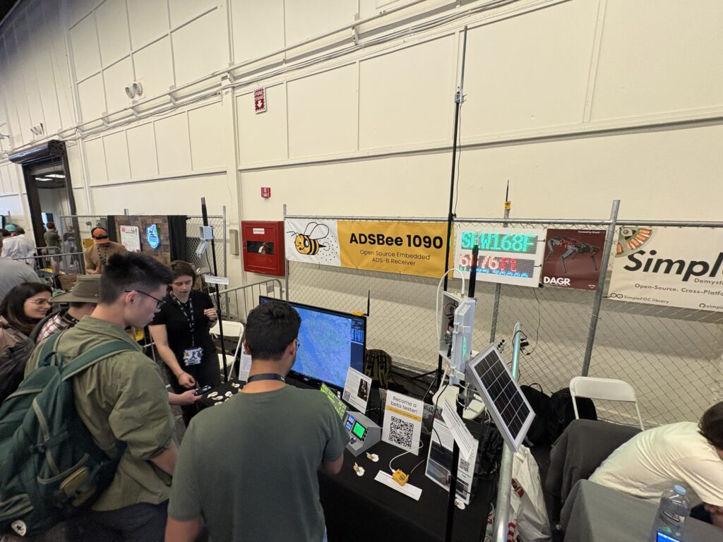
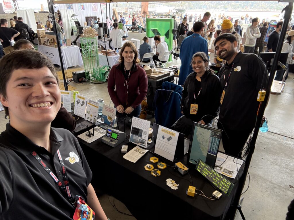
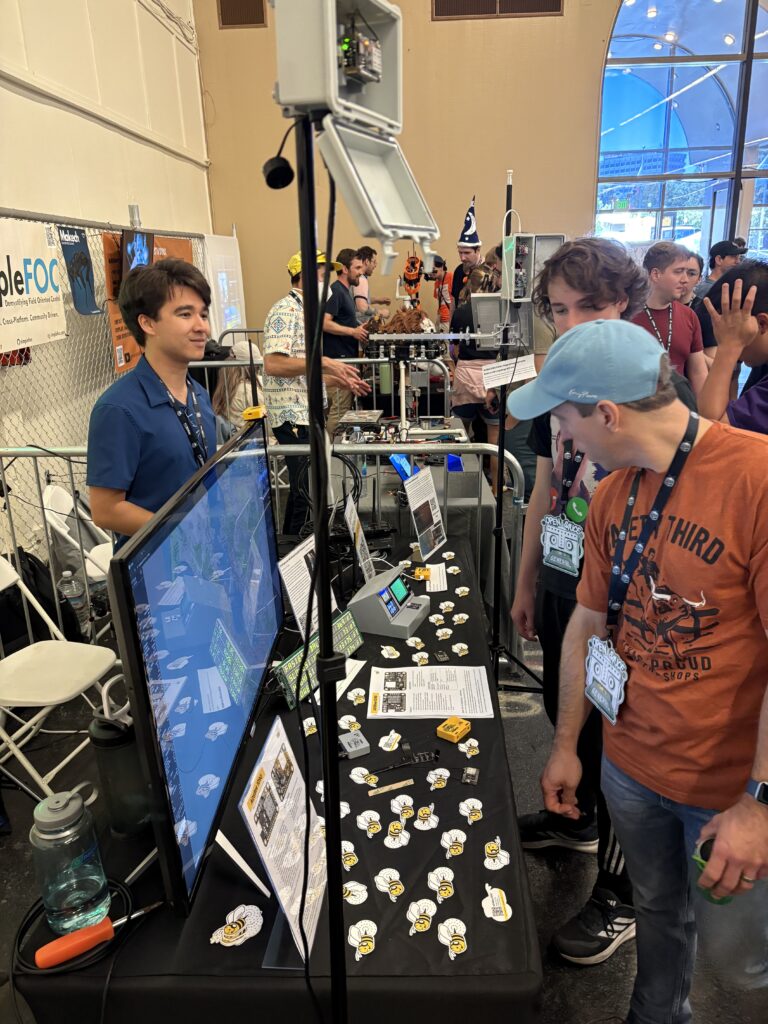
I had the exciting opportunity to exhibit ADSBee 1090 at Bay Area Maker Faire. Many thanks to my friends who helped staff the booth, and another thank you to those of you who stopped by to say hi and learn about the project!

Booth, with friends!

From Mare Island we were able to see aircraft as far away as Modesto. I had hopes that our table might have a good view of SFO, but alas we were situated in a brick building surrounded by metal and electrical equipment. The direction of SFO was blocked by multiple large brick and concrete industrial buildings as well as a hill, so we didn’t have a chance to see much of anything in that direction, but we did pick up lots of aircraft towards the east!

The banner stand and antenna mount behind the booth was janked together with some 3D printed brackets, wood from Home Depot, and some used lighting stands that I bought from Facebook Marketplace the day before. The lighting stands allowed me to mount a 5.5dBi colinear dipole antenna just above the metal fence that was behind our booth, providing reasonable eastward reception and enough aircraft to make the interactive flight display somewhat interesting to look at.

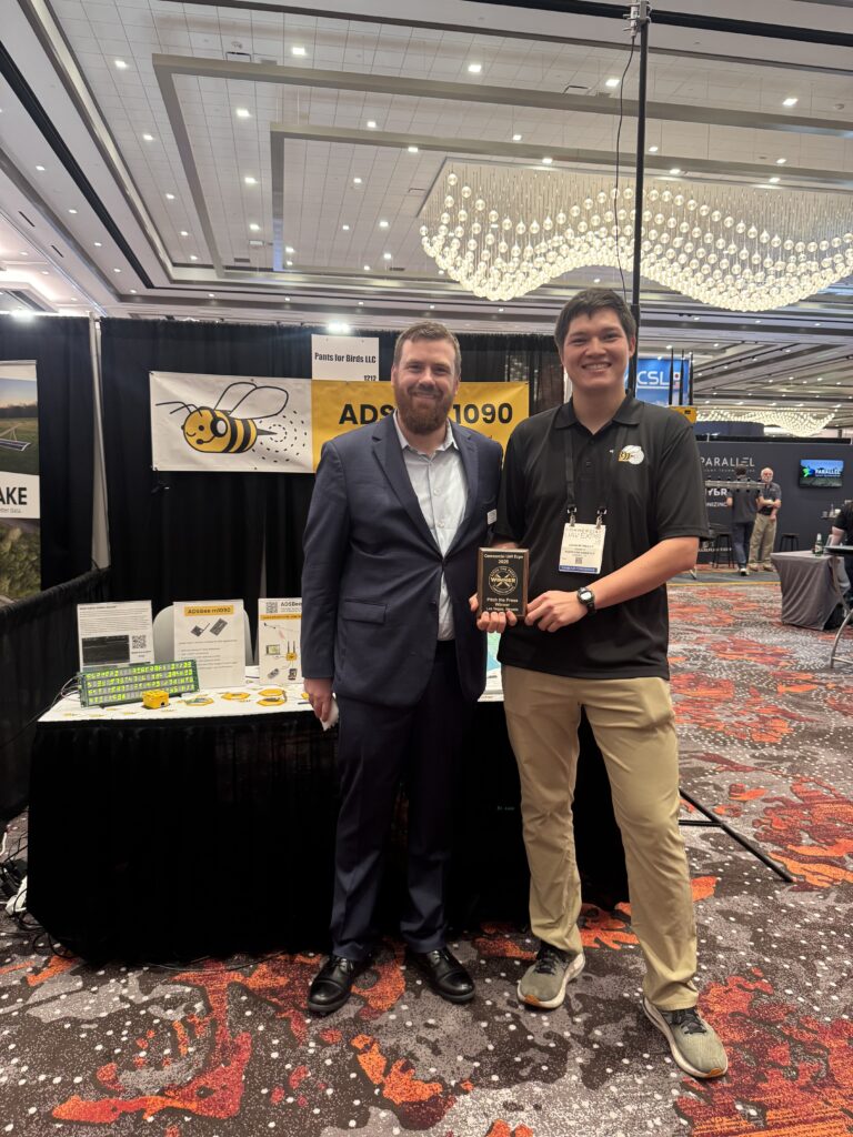
To my delight and surprise, we were selected to receive an editor’s choice award! The friendly editor of Make Magazine gave us a little blue ribbon and a modest but certainly appreciated sense of accomplishment.

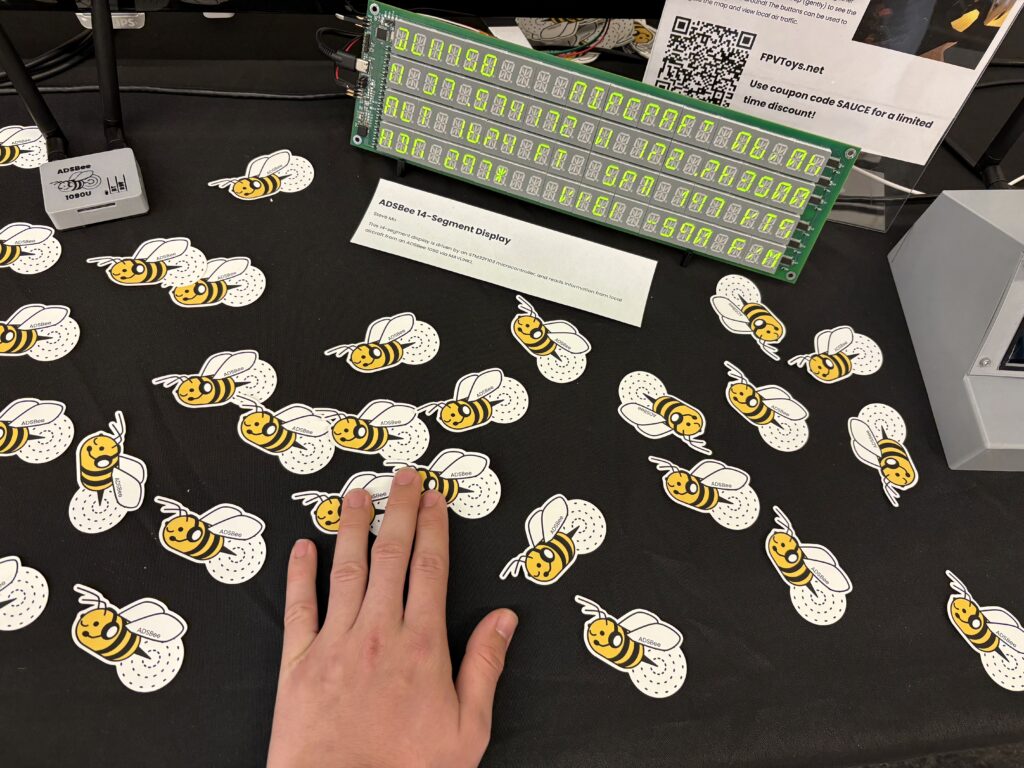
We must have given out at least 600 ADSBee stickers during the course of Maker Faire, so if you see them appearing on various belongings owned by children and/or turbo nerds located in or adjacent to the Bay Area, it’s a good bet that you know they came from!

ADSBee 1090 in the field 🌾✈️

I brought the ADSBee 1090 along with me to two airshows and a number of trips to the local airport. Can’t miss a good opportunity for data gathering!

Manufacturing in Progress! 🏭

Manufacturing of the Beta batch of ADSBee 1090’s is in progress! As of the writing of this post, all PCBA assembly and initial program / test is complete. The remaining time before ADSBee ships will be utilized for cramming in some last-minute firmware improvements and additional testing to try screening out potential manufacturing defects that may not have been noticed during program and test.

Qualifying the first 10 PCBs off the line.
PNP machine go zoooom.

Posted on Leave a comment

ADSBee 1090 September Update

This last month has been another solid wave of progress! ADSBee 1090 Rev F is looking good and I’m excited to see it move into low volume initial production very soon. Scroll to the end for an update about the ADSBee Beta! 🎉

Hardware Updates

ADSBee 1090 Rev F Bringup

Bringup of revision F of the ADSBee 1090 has proceeded quite smoothly! There were a few hiccups (I had the wrong component installed by the manufacturer for the bias tee switch MOSFET, and some of the components that I’ve had to manually populate have been difficult to solder down properly), but overall the board seems to function as intended. Major changes in this revision include:

  • Redesigned RF frontend with new layout and extra gain + SAW filter stage.
  • Completely redesigned analog circuit implementing a data slicer topology.
  • Upgraded to a newer ESP32 (ESP32-S3).
  • Rewired the inter-processor communication bus to not accidentally use reserved pins on the ESP32.
  • Added a USB JTAG debug connector for programming the ESP32, and added a coprocessor SPI connector to enable addition of a UAT module at some point in the future.
  • Redesigned RP2040 pinout to expose pins for a second PIO state machine from the preamble detector and demodulator PIO blocks.

With this many changes, I have been pleasantly surprised to not find any “deal breakers” so far! It appears that all 10 of the PCBs I received will be able to be used as functional devices for testing once they are fully assembled and tested.

ADSBee 1090 Rev F hardware should be sufficient for the needs of our hardware Beta! Most of the units I have hand-assembled will be used for testing internally, but a select few will be sent out to other developers participating in the Beta test. I currently am getting assembly quoted for an additional run of Rev F units, which will be made available for a larger beta as soon as I have an updated estimate of pricing.

ADSBee 3D Printed Enclosure

I designed a 3D printed enclosure for the ADSBee 1090, with enouh extra room to support an FPC WiFi antenna and external GNSS module, and openings for connectors and indicator lights, button flexures for the BOOT and RESET buttons, and an internal latch to keep it closed. It’s still a work in progress, but the OnShape designs are available below. Feel free to remix and improve the enclosure as you see fit! I’d love to hear about new designs.

ADSBee 1090 Enclosure

ADSBee 1090 Bare PCB (Rev F)

Antennas and Cables

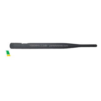
The 1090MHz sleeve dipole antenna has been redesigned to use a much smaller outer housing. This should make the full device more compact, and will have an added benefit of saving on shipping costs.

Waterproof SMA to U.FL cables have been sourced and tested, and are currently in 100x production to support the hardware beta. My intention is to include waterproof SMA to U.FL cables in order to allow ADSBee owners to easily connect their ADSBee to a 1090MHz antenna from within a waterproof enclosure. The cost difference between waterproof and non-waterproof SMA bulkhead connectors is relatively small, so it makes sense to standardize on a single cable part for waterproof and non waterproof enclosures in order to lower the unit cost.

Flex PCB WiFi antennas have also been sourced and tested. They will eventually need to be custom tuned for their installation location relative to the ADSBee 1090 PCB within the 3D-printed enclosure, but they should function just fine for the beta without the need for fine tuning.

Firmware Improvements

Additional Mode S Downlink Formats

Decoding has been implemented for Mode S downlink formats 4 and 5 (Identity and Altitude replies). This was a bit of an adventure, and involved a fairly cursed exploration of how to decode Gillham Coded altitude information (old timey altitude encoders connected directly to transponders with a number of parallel wires, and used a novel binary protocol that was intended to only toggle a single bit at a time while incrementing or decrementing). Many thanks are owed to a kind British man named Kevin Stewart, whose old forum posts and online documentation described how to decode Gillham coded values in the context of his quest to build a DIY altimeter calibration device.

Gillham Codes have no built-in method of error checking, since a single broken wire in the bundle of wires between the altitude encoder and transponder can cause garbage altitude values to be transmitted. There is a single bit flag in the Mode S protocol that is dedicated to warning that a transponder’s altitude information may not be very robust, as it is based on a single reading from a Gillham coded altimeter.

Gillham coded transponder outputs (just a bunch o’ wires) have since been superseded by a number of more robust communication protocols between altimeters and transponders on aircraft (e.g. serial protocols with checksums), but for some reason the Gillham codes themselves are still used for encoding altitude data in 56-bit Mode S packets.

An old-timey transponder that uses Gillham Codes.

Decoding has also been added for Navigation Integrity and Navigation Accuracy information provided by aircraft via ADS-B (Mode S downlink format 17). This should provide some additional interesting details, such as the approximate dimensions of an aircraft (when on the ground), as well as a number of numerical values which describe the robustness of the location information provided by the GNSS system on board the aircraft.

CSBee Protocol

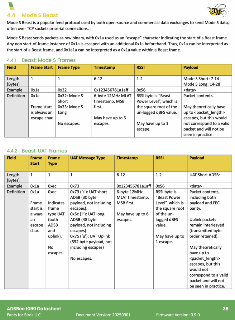
CSBee (Comma Separated Bee values) is an information-rich plain text protocol based on the popular Aerobits CSV protocol, but with a number of additional fields. A PDF excerpt from the draft datasheet describing the CSBee protocol is included below.

Oversampling in PIO!

One of the issues that I’ve encountered repeatedly with decode performance has been that spurious noise can cause the PIO preamble detector or demodulator state machines to follow a stray edge into the wrong state, causing offsets in recovered clocks and garbled bits. After a few weeks of hard thinking, I convinced myself that it might be possible to refactor the PIO code to include oversampling (sampling the digital input signal from the data slicer circuit multiple times and then taking a majority-wins approach to classifying state of the pin as HI or LO). What followed was many days of PIO assembly hell and some rather difficult debugging, but I’m very happy to report that oversampling works, and seems to yield a significant improvement in both the integrity of detected preambles as well as the success rate at decoding Mode S messages! I neglected to get real numbers, but by John’s precision vibeometer I can confirm that the decode rate has improved by something like 2x-4x in most cases.

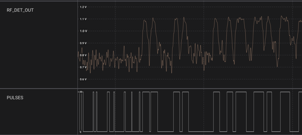
Oversampling in action! Top (orange) is the raw analog output of the power detector. Yellow is the output of the data slicer circuit, turning the power detector output into a clean HI or LO. Green is a debug output from the demodulation PIO. The triple pulse indicates the 3 samples being taken, and the single pulse following indicates that the bit was classified as a 0 (LO->HI transition). If there are two pulses following the triple pulse, it indicates that the bit was classified as a 1 (HI->LO transition). This example isn’t especially compelling since the data slicer output is clean, but the majority-wins oversampling implementation creates significant improvements in decode performance when dealing with noisy data.

Inter-Processor Communication

To address the need for bidirectional communication between the RP2040 and ESP32, I implemented a custom SPI protocol. This took a bit longer than I anticipated, and was slightly over 1000 lines of code once everything was tested and working. The main complexities derived from communication being asymmetric (the RP2040 is the master and can talk whenever it likes, whereas the ESP32 is a slave and has to request communication explicitly from the master), and breaking large transactions into smaller 64-Byte chunks that could be easily handled by both the RP2040 and ESP32 without the need for huge buffers. The protocol is mostly going to be used for very frequent short communication between processors, as the RP2040 streams transponder packet information to the ESP32, but also must be able to handle medium sized data transfers (like sending over a few hundred byte large struct containing settings information) and larger data transfers (eventually, a full firmware image up to 16MB in size might need to be shuffled over SPI from the ESP32 to the RP2040 for an OTA update).

Initial tests seem to show the protocol working well! I’ve included a short GIF of transfers between the RP2040 and ESP32. Transfers shown in the GIF tested sending data with and without forced acknowledgements, writing and reading from a scratch register, and transferring large blocks of data that had to be broken into multiple messages.

🎉ADSBee Beta🎉

The primary factor gating the ADSBee Hardware Beta has been receiver performance. I didn’t want to send out units that I wasn’t sure that beta testers would be excited to use, and predictably, the majority of that boiled down to whether the ADSBee 1090 was good at receiving ADS-B and Mode S packets. Over the course of the last month, testing results have convinced me that the significant overhaul of receiver hardware in the transition from ADSBee 1090 Rev E to Rev F and the impactful improvements made to ADSBee decode logic have reached the performance targets necessary to begin manufacturing for the ADSBee Hardware Beta.

In my testing, while the ADSBee 1090 isn’t as sensitive as the best software defined radios that have dedicated pre-filters and LNAs targeted for use exclusively on 1090MHz, the ADSBee 1090 is approaching performance parity with extremely common unfiltered SDRs (like the RTL-SDR V3) and existing (much more expensive) embedded receivers like the uAvionix PingRx. I’m not yet done improving the decode logic, and I have a few more things in the pipeline that will hopefully improve receive performance further–but I’m convinced that Rev F hardware will be up to the task as-is for many of the applications that users have been excited about!

Performance comparison between an ADSBee 1090 and a uAvionix PingRX running off of the same antenna:

ADSBee 1090 (left) vs uAvionix PingRx (right) showing aircraft dictionaries when connected to the same antenna.

Performance comparison between an RTL-SDR v3 dongle and an ADSBee 1090 running off of the same antenna:

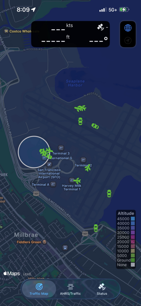
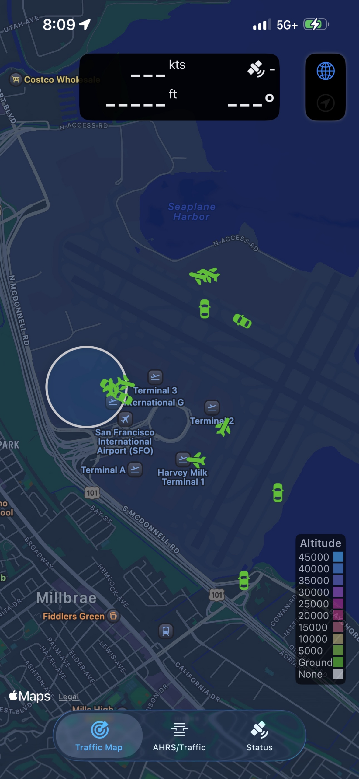
Phone screenshot from portable ADSBee 1090 testing outside of SFO:

Receiving 40 aircraft from a handheld receiver on the outskirts of San Francisco International Airport!

OK that’s cool dude but when is the Beta?

Pre-orders for ADSBee Beta units will be opened soon, once I have solid quotes back from my contract manufacturer for Revision F of the PCBA. I expect pricing to be in the sub $85 range. All Beta units will include a 3D printed case, SMA antenna connector, WiFi antenna, and 1090MHz antenna. If manufacturing proceeds smoothly, the lead time for beta units will be about 1 month after preorders close.

In the meantime, I have a few hand-assembled units that will be made available to developers. If you are interested in contributing to firmware, please reach out to me on Discord and I’ll see about getting you some hardware!

Posted on Leave a comment

ADSBee 1090 August Update

I’ve been working hard on ADSBee 1090 since the July update. Here’s what I’ve been up to since y’all last heard from me!

TL; DR Redesigned the analog and RF frontend of the ADSBee 1090, new rev with cool features (ADSBee 1090 Rev F) coming soon. Also, lots of firmware work! Hardware beta details still TBD pending bringup of the new rev.

Testing ADSBee 1090 Rev E

In late July, I took some ADSBee 1090 Rev E PCBAs with me on a trip, and had a grand time collecting aircraft contacts and adding features to the RP2040 firmware. Important additions include bringup of our new 64kbit EEPROM (which should be large enough to store any feeder IP addresses, WiFi passwords, etc. that we might need), addition of Mode S Beast protocol as serial output, and implementation of a high resolution 12MHz timer for multilateration (with wonderful assistance from one of our community members, @gwoplock).

Receiving contacts from the 7th floor of a cruise ship. Maximum contact range that I saw was about 160 miles!

During the course of the trip, I was able to demonstrate some rather long range contacts even with a relatively primitive base station setup, but I did notice that the receiver performance suffered when aircraft were too close to the receiver. Once I got back home, I started some relatively squishy / qualitative benchmarking against a few software defined radio dongles and an off-the-shelf FPGA-based receiver (uAvionix PingRx). While the results weren’t very precise, it became apparent that some improvements to the ADSBee 1090’s receive performance would be necessary for the device to be a competitive solution. After a few weeks of using ADSBee 1090 Rev E, it was also clear that there were a few too many knobs that required fiddling from the user (receive gain adjustment, positive and negative trigger thresholds), which indicated unnecessary complexity and room for improvement in the UX. Thus began a few weeks of some pretty aggressive redesign of the RF frontend and analog circuitry on the ADSBee 1090, culminating in releasing ADSBee 1090 Rev F to manufacturing yesterday (2024-08-17).

Analog Redesign

Analog circuitry redesign consisted of etching some teeny tiny PCBs (bodge boards) in my garage with room for a few analog components, then VHBing the bodge board onto the back of an ADSBee 1090 and tapping into the circuit via test points or pads on the front of the board. I iterated through four separate analog designs before I finally settled on a relatively popular topology called a Data Slicer (commonly used for decoding an AC Manchester coded signal with some level of DC bias). This topology has the side benefit of removing an op amp and analog switch from the circuit, which frees up space and BOM cost for RF frontend improvements.

The final design no longer requires a user to set receive gain and two trigger thresholds, since it automatically adjusts to fit the signal amplitude of aircraft at various ranges, and only requires a single adjustable DC bias that can be set to properly ignore the noise floor. My hope is that most users will never have to change this value, which will be set to a reasonable default in firmware, and may only need to adjust it if they are doing some advanced maneuvers before the ADSBee 1090’s RF input, like adding a cavity filter or an additional Low Noise Amplifier (LNA).

Data Slicer in action decoding a message. Green pulses are the RF power detector output, Blue line is the slow adjusting comparator trigger threshold, and Yellow line is the pulse train being sent to the demodulator PIO. Orange pulse train at the bottom is the recovered clock signal being emitted by the RP2040.

RF Redesign

Poking and prodding at the ADSBee 1090 Rev E circuit has indicated that range for the ADSBee 1090 can be significantly improved through an additional LNA gain stage. I etched a PCB to allow the addition of said gain stage using the same LNA part number as already exists on the ADSBee 1090 (Berex BLB01), and also evaluated performance with an off-the-shelf LNA. Both LNAs yielded a significant increase in number of aircraft tracked, so I’m excited to see what end to end performance looks like with a properly integrated dual gain stage RF frontend.

Home etched test board with a BLB01 LNA.

In addition, I etched some test boards for qualifying an alternative SAW filter from another manufacturer that promised similar performance characteristics with slightly lower insertion loss. Through some supply chain finagling, I’ve been able to get pricing for SAW filter components down from ~$15 each at 100x quantity (crazy, absurd, absolutely wild) to the $1 range. If people are interested in some 1090MHz SAW filter boards (just the filter and some connectors, nothing else), shoot me a message on Discord or via email and I can look at cooking up a group buy of some properly laid out and enclosed filter PCBAs.

ADSBee Rev F’s RF frontend includes a number of the goodies above, with two cascaded LNA and SAW filter stages. I’ve also moved the first SAW filter stage behind the first LNA stage in an attempt to improve SNR in typical environments. This means that if you’re in a really, really noisy environment or have a relatively wideband antenna, you might need an additional filter in front of ADSBee 1090, but I think this will be a relatively rare occurrence.

I also added test ports to enable proper characterization of gain and noise factor of the ADSBee 1090’s RF signal chain, as well as characterization of the narrowband input match on the AD8313. This will hopefully allow me to flesh out any gremlins that might still be hiding in the RF frontend and hindering receiver performance.

Lastly, a switchable bias tee circuit (3.3V out, 200mA) was added to the RF input to allow the ADSBee 1090 to power an external LNA before its first stage, if so desired. I don’t anticipate many users needing this feature, but for now, it’s there if someone wants it!

ADSBee 1090 Rev F

Here it is! Rev F looks pretty similar to Rev E on the surface, but includes the following improvements:

  • Overhauled analog circuitry with a design that automatically adjusts sensitivity to different transmit power levels. This should hopefully remove the “doughnut effect” we were seeing on Rev E, which made the receiver only sensitive to aircraft in a relatively narrow band of radial distances. The new circuit uses fewer expensive components (no op amp or analog switches), so this BOM cost and board space savings has been reinvested into improvements to the RF frontend.
  • Moved to a two-stage amplifier with double SAW filters. Added MHF3 connectors for characterizing noise figure of the RF input stage and characterizing the narrowband impedance match of the AD8313. I’m hopeful that we can improve our signal to noise ratio by a few dB here.
  • Provisions for utilizing 2x PIO state machines as interleaved demodulators. In theory this could let us keep scanning for preambles even in the midst of decoding a message.
  • Fixed an ESP32 SPI trace issue that was causing crashes (SPI lines were previously shared with ESP32 internal flash memory).
  • Added ESP32 JTAG USB connector.
  • Switchable bias tee for external LNA.
  • JST-SH connector footprint for connecting to another board via the coprocessor SPI bus plus a few GPIOs. The hope is to use this for development of a UAT receiver add-on at some point down the road.
  • Switching the EMI can to a two-piece design that allows the cover to be removed and replaced without desoldering anything.

I’m excited to get my hands on a few of these boards to see what they can do. Feel free to follow the adventure on Discord, or check in for an update next month! If Rev F proves itself Worthy, the ADSBee Hardware Beta will kick into drive in earnest. Thank you to all of our (very patient) Beta testers!

If you’d like to join the mailing list for the Hardware Beta (if you got this update as an email, you’re already on it), feel free to sign up here.

Posted on Leave a comment

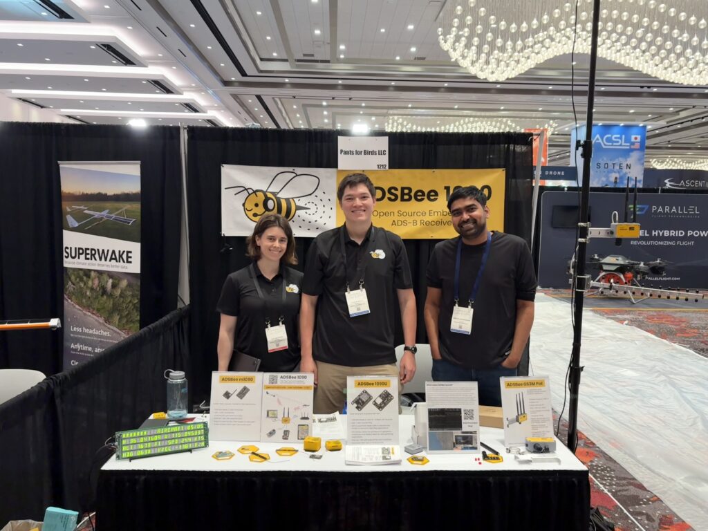
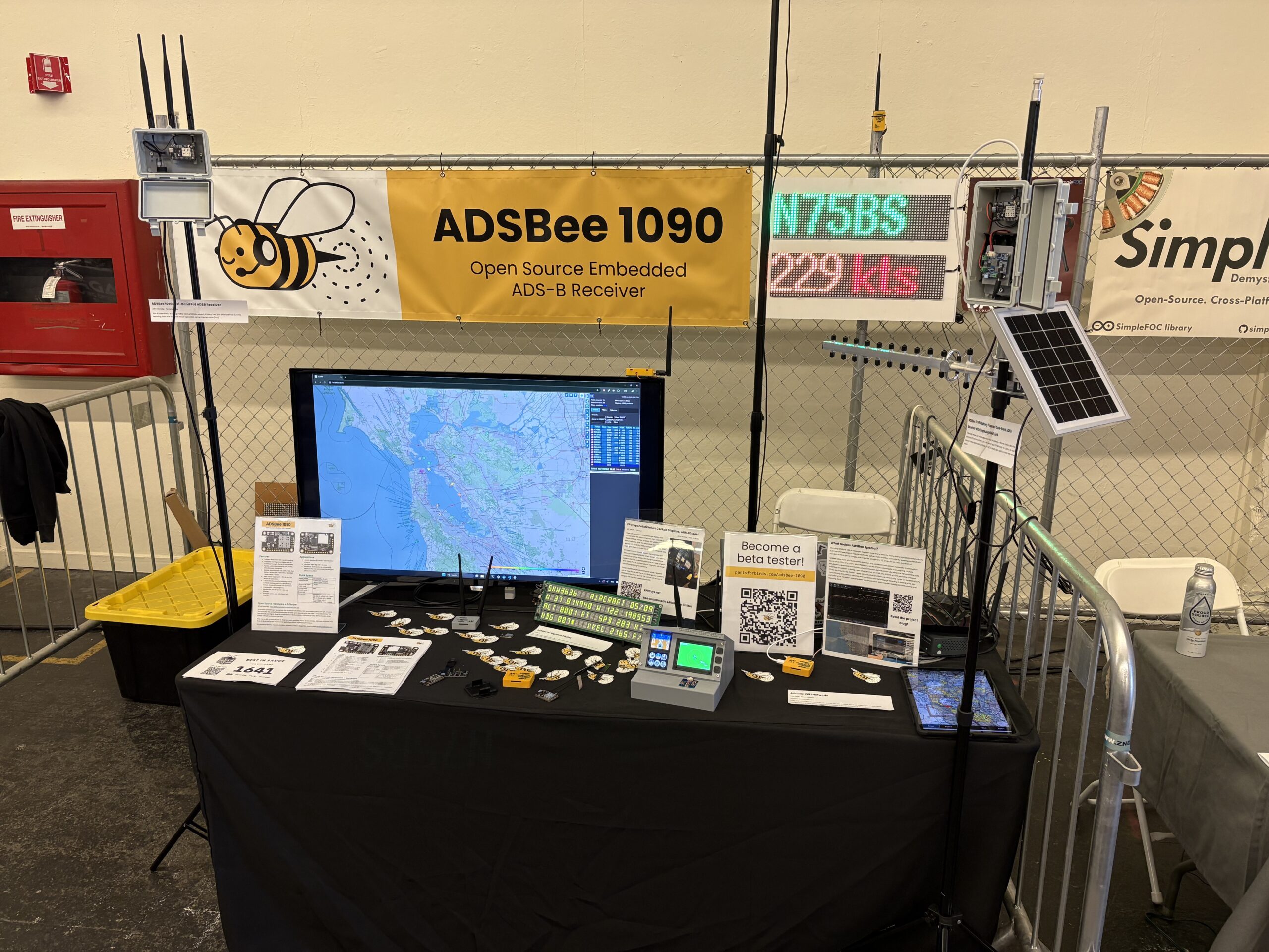
Pants for Birds at Open Sauce 2024

Pants for Birds will be at Open Sauce 2024! I will be showcasing some ADSBee 1090 units, and hanging out with some cool friends who are bringing projects of their own:

  • Giant LED panel info display displaying aircraft information.
  • Snake! Running on a factorio CPU with a real-life interactive LED display / arcade panel.
  • Team Mario Kart: Mario Kart, but if each kart was being driven by two squirrels, one of whom controlled steering and one of whome controlled acceleration.
  • Interactive ADS-B data visualization written in a very cool upcoming open-source data visualization tool.

Say hi if you see us!

Posted on Leave a comment

Hello World!

After doodling around with projects for a few years under the Pants for Birds name, I’m excited to announce that Pants for Birds is now a registered California LLC! I’ve changed my day job to part-time status, and will be pursuing commercialization of open source hardware products under the Pants for Birds brand.

The first “real” product will be an open-source ADS-B receiver based on the RP2040 microcontroller. This project has been warming in the oven for a number of years, and I’m excited to boot it across the line and turn it into a fully featured product. Let’s see how this goes!